AutoCAD: Linetypes

Like lineweight, linetype is a property assigned to layers, and by extension, to objects assigned to those layers. Although it’s considered good practice to use layers to organize object linetype, object lineweight is often set on a per-object basis.


LINETYPE SCALE IN AUTOCAD.

All AutoCAD linetypes, with the exception of the default CONTINUOUS linetype, are subject to the LTSCALE system variable. As a general rule, if LTSCALE is increased, the size of the pattern (e. g. the dashes in the line) will increase. However, each different LINETYPE bears a different relationship to LTSCALE. For example, if you set LTSCALE to 1, the DASHED linetype looks like this:
linetype-dashed
Meanwhile, the HIDDEN linetype looks like this:
linetype-hidden
A good rule of thumb for LTSCALE is as follows. Consider the scale at which you’ll print the drawing. Convert this scale to a ratio (e. g. 1/4” = 1’-0” is equivalent to 1 : 48). Set LTSCALE to the right half of this ratio (in this example, to 48). This rule works because if you print your drawing at a comparatively small size, the dashes in the lines should be large relative to the size of objects in the drawing.


TO LOAD A LINETYPE INTO A DRAWING:

1.     Type LINETYPE.

2.     In the resulting Linetype Manager dialog box, click Load.

3.     Choose the linetype you want to load and click OK.

4.     Click OK again to close the dialog box. The linetype is now available to be assigned to layers and/or objects (see below).


TO CHANGE LINETYPE ON A PER-OBJECT BASIS:

1.     Load a linetype into your drawing. (See above.)

2.     From the View tab, Palettes panel, click Properties to display the Properties palette.

3.     Click on an object, or a group of objects. Click next to the word “Linetype” in the Properties palette and select a new linetype from the pulldown menu. Click the escape key to deselect the object(s).

AutoCAD: Layers

Every object in AutoCAD belongs to a layer. A layer can be made invisible, causing the objects assigned to that layer to disappear from view (this is called turning a layer off). A layer can be locked, protecting the objects assigned to that layer from accidental erasure or displacement. A layer can be defined as non-printing, so that its objects are visible on screen but do not print.


TO CREATE A NEW LAYER:

Type LAYER. In the resulting Layer Properties Manager dialog box, use the New button to create and name a layer; use the Current button to choose a layer for drawing (newly drawn objects appear on the current layer); use the color swatches to assign colors to layers.


TO DELETE A LAYER:

In the Layer Properties Manager dialog box, highlight a layer name and click Delete. If the layer contains objects, it cannot be deleted. Typing PURGE at the command prompt will omit unused layers.


TO CHANGE AN OBJECT’S LAYER:
Use any one of these methods:

Type CHANGE (or –CH). When prompted, select the object(s) and click enter. Type P for Properties; LA for Layer; and then the name of the layer to which you wish to assign the object(s).

OR use the layer pulldown menu in the Object Properties toolbar. Click the object(s); then click the pulldown menu and release the mouse over the layer to which you wish to assign the object(s). Click the escape key to deselect the object(s).

OR click ctrl-1 to display the Properties palette. Click on an object, or a group of objects. Click next to the word “Layer” in the Properties palette and select a layer from the pulldown menu. Click the escape key to deselect the object(s).

OR use the MA (“match properties”) command to assign the properties of a source object, including its layer assignment, to one or more other objects.


AutoCAD: Function Keys

In AutoCAD, the function keys (except for F1 and F12) act as switches or toggles. Of all the function keys, F3 (object snap) and F8 (“ortho”) tend to be the most frequently used. The others tend to be used comparatively rarely.

F1 brings up AutoCAD’s Help.

F2 opens and closes the Text window, which is simply an expanded version of the command window. It provides no additional functionality other than the ability to look back at what you just typed.

F3 turns the object snap function on and off.

F4 turns a peripheral drawing tablet (if connected) on and off.

F5 cycles between isometric planes. This function is used for creating isometric drawings. (To experiment with this, type SNAP, change the Style to Isometric, and draw some lines. Use F5 to cycle between planes.) Also see F9.

F6 cycles between coordinate displays, at the bottom left-hand corner of the screen.

F7 turns the drawing grid on and off. To specify the gird extents, type LIMITS. To specify the grid spacing, type GRID.

F8 turns the orthographic lock function on and off.

F9 turns the automatic snap function on and off. When on, AutoCAD snaps to an invisible rectangular or isometric grid, not necessarily the same grid as specified using the GRID command. To specify the snap settings, type SNAP.

F10 turns polar tracking on and off. It also automatically turns F8 (ortho) off. Polar tracking displays angles and distances while drawing.

F11 turns the automatic object snap tracking function on and off.

F12 has no function.


AutoCAD: Lineweights

Lineweight is the visual thickness of lines. The use of lineweight is critically important to maintaining good legibility and professional appearance in drawings. See this post for general information on lineweight.

In AutoCAD, lineweight is an object property, meaning that every object in an AutoCAD drawing can be assigned its own lineweight. By default, every object is assigned the ByLayer lineweight, meaning that the object assumes the lineweight assigned to its layer. Like any object property, this can be overridden on an object-by-object basis.

It’s considered good practice to use layers to organize object lineweight, rather than setting object lineweight on a per-object basis. In other words, unless there is a compelling need to do otherwise, always keep AutoCAD object lineweight set to ByLayer.


TO CHANGE LINEWEIGHT OR LINETYPE ON A BYLAYER BASIS:

1.     Load a linetype into your drawing. (See above.)

2.     Type LAYER to bring up the Layer Properties Manager palette.

3.     Click on the layer whose properties you wish to change.

4.     Choose the desired linetype or lineweight. All objects in this layer with the BYLAYER property set for linetype or lineweight will inherit these settings.


AutoCAD: Selection

Many AutoCAD commands will prompt you to Select objects. The following are acceptable methods of responding to the Select objects prompt. Each time you add an object to the selection set, it is highlighted (i. e. it appears dashed). When you are finished selecting objects using any one or a combination of these methods, press [Enter] to continue the original command.


TO SELECT OBJECTS:

Click on objects one-at-a-time.

OR draw a window around the object(s). AutoCAD uses a click-click method to define a selection window, rather than the standard click-drag-release. “Standard” selection windows are drawn from left to right, and select only those objects completely within the window. “Crossing” windows are drawn from right to left, and select all objects within and contacted by the window.

crossing_standard_01

OR type F (for Fence), and draw a selection line (a “fence”). Like a crossing window, a fence selects any objects it touches. This method is useful for making precise selections in restricted areas.

OR type P (for Previous). This selects whatever object or objects were previously selected.

OR type L (for Last). This selects whatever individual object was last selected or created.

OR type U (for Undo). Deselects the last object(s) selected. Use this if you make a mistake while defining a complex selection set.

OR type ALL. Selects everything in the current space.

OR type R (for Remove). Switches the selection mode from “adding” to “removing”. Type A (for Add) to switch back. Use this function while defining a complex selection set.


PRESELECTING OBJECTS:

It is possible to preselect objects before issuing commands. This technique is frequently useful in 3D (three-dimensional) work, but it can be used in 2D as well.

To preselect an object or objects, click [esc] two or three times in succession, and then either click on objects one at a time or window several objects at once. As you preselect more objects, they display highlighted (i. e. dashed) with grips. Grips are like “handles” at object corners and other critical points. You can click on highlighted grips to stretch and move objects.

After an object has been preselected, you can issue any modifying command (such as ERASE, MOVE, COPY, etc.).

To clear preselected objects from the selection set, click [esc] two or three times in succession.

AutoCAD: Commonly Used Commands

AutoCAD is a command-driven software application, meaning that it responds to commands typed after the Command prompt at the bottom of the screen. Commonly used commands (and equivalent keyboard shortcuts) are as follows:


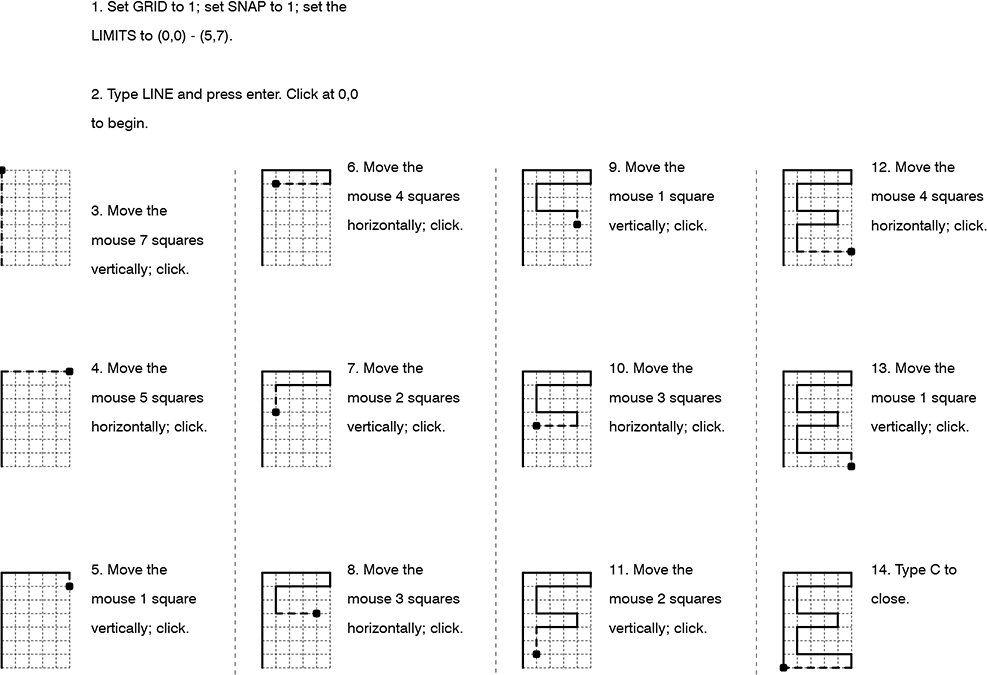
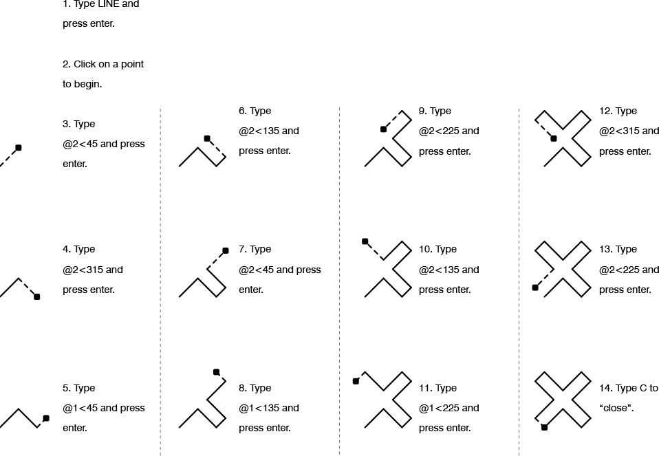
LINE (L): The LINE command draws straight lines between specified points. The command will keep prompting you to enter points until you terminate the command by clicking the esc key (or by clicking Enter without indicating a point).

line_01

Hint: Use the [F8] key to restrict lines to orthogonal directions.

Ribbon: Home > Draw > Line


ERASE (E): The ERASE command erases objects. The command will prompt you to select objects.

Ribbon: Home > Modify > Erase


PAN (P): PAN has the same effect as clicking on the scroll bars at the edge of the window, or holding down the center mouse wheel and moving the mouse.

Hint: Every once in a while, AutoCAD will prevent you from panning your view too far in one direction; the screen will “stick”. To get around this, click esc a few times in succession, and then type RE (for Regenerate). This forces AutoCAD to regenerate the drawing display, expanding the area over which you can pan.

Note: To invoke a “legacy” version of the PAN command, type -PAN (hyphen PAN) or -P. This is a useful and more precise variation of the command; it operates analogously to MOVE.

Ribbon: View > Navigate 2D > Pan


ZOOM (Z):  ZOOM works like a magnifying glass; use it to enlarge or reduce the apparent size of the drawing. Note that ZOOM does not change the actual size of the drawing – just its appearance. Typing ZOOM at the command prompt, and then choosing the Realtime option, has the same effect as spinning the mouse wheel.

Hint: As with the PAN command, AutoCAD will occasionally prevent you from zooming your view too far in or out. If this happens, click esc a few times in succession, and then type RE (for Regenerate). Ultimately, there are limits to how far you can zoom in or out (try and find these).

Hint: Typing Z, for Zoom, followed by E, for Extents (that is: Z-enter-E-enter), causes AutoCAD to zoom out to the full extents of your drawing. Z-enter-A-enter has a similar (though not identical) effect.

Ribbon: View > Navigate 2D > Zoom


MOVE (M): The MOVE command moves objects, translating them from one point to another. The command prompts you to select objects, and then it prompts you for a base point. The base point can be any point in the drawing, not necessarily on the objects being moved. The command then asks for a second point (a displacement point). The objects are erased from their original location.

move_01

Ribbon: Home > Modify > Move


COPY (CO): The COPY command differs from ctrl-C in that it includes a “Paste”-like operation. COPY is fundamentally the same as the MOVE command except that the original objects are not erased from their original location. Also, COPY allows you to make multiple copies at one time: to do this, type M after you’ve completed selecting objects.

copy_02

Ribbon: Home > Modify > Copy (different than using ctrl-C to copy)


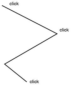
TRIM (TR): Use the TRIM command to “cut” an object with another object. For example, two non-parallel lines can be used to cut each other. The command will prompt you to select “cutting edges” (you can select as many edges as you want). After you’ve selected edges, the command will prompt you to select the objects to trim. Click on the part of the object you want to have disappear.

trim_01

Hint: When selecting objects, type ALL, or simply press enter at the first prompt to select objects. Then, when selecting objects to trim, every object in the drawing can potentially trim every other object in the drawing.

Hint: Type EDGEMODE at the Command prompt to switch between two different settings (0 or 1): when set to 0, objects must be in contact to trim one another.

Hint: When selecting objects to trim, type F (for Fence). See section 1.4 for more on this.

Hint: When using the TRIM command, hold down the Shift key to change its function to EXTEND.

Ribbon: Home > Modify > Trim


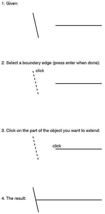
EXTEND (EX): EXTEND is the “reverse” of TRIM. The command prompts you to select “boundary edges” (you can select as many edges as you want). After you’ve selected edges, the command will prompt you to select the objects to extend. Click on the part of the object you want to extend.

extend_01

Hint: When using the EXTEND command, hold down the Shift key to change its function to TRIM.

Ribbon: Home > Modify > Extend


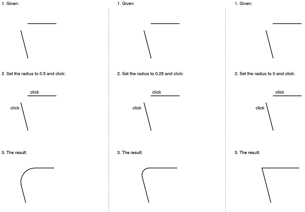
FILLET (F): The FILLET command can be differently understood as a combination of the functions of EXTEND and TRIM, and/or as a means of providing rounded connections between lines. The command always operates on two independent objects. Its operation is constrained by its radius setting. (To change the fillet radius, type FILLET, and then type R for radius.)

fillet_01

Ribbon: Home > Modify > Fillet


CIRCLE (C): CIRCLE draws circles by one of several methods, e. g. the default center-radius method.

circle_01

Hint: Sometimes, AutoCAD will temporarily display circles as polygons (octagons are common substitutes). This is a time-saving device built into the program. To display the circles correctly, type RE (for Regenerate).

Ribbon: Home > Draw > Circle


ARC (A): ARC draws arcs by one of several methods. When using the center-start-end method, note that arcs are drawn counterclockwise.

Hint: Sometimes, AutoCAD will display arcs as line segments. To display the arcs correctly, type RE (for Regenerate).
Ribbon: Home > Draw > Arc


OFFSET (O): OFFSET is used to create parallel lines and concentric curves. It operates on one object at a time. The general procedure is: type OFFSET; click on the object; specify a distance; finally, click off to one side of the object (e. g. left side or right side, top or bottom).

offset_01

Ribbon: Home > Modify > Offset


TEXT (DT) and MTEXT (T). The TEXT and MTEXT commands are used to add text to drawings. TEXT adds text one line at a time; MTEXT operates more like a word processor, with greater control over editing. Both commands are subject to the settings in the STYLE command: use STYLE to set basic attributes for fonts.

Important: When you use the STYLE command to define a New Style, it’s usually a good idea to define the style to have a text height of 0. This ensures that AutoCAD will prompt you to enter a text height every time you try to add TEXT or MTEXT.

Ribbon (TEXT): Annotate > Single Line Text
Ribbon (MTEXT): Annotate > Multiline Text


MIRROR (MI): MIRROR is used to create a “reflection” of existing objects around a line. Define this line with any two points in the drawing.

Ribbon: Home > Modify > Mirror


ROTATE (RO): ROTATE will rotate any selection set of objects around a fixed point. Note that AutoCAD measures degrees counterclockwise, with “0 degrees” corresponding to a “3 o’clock” position.

Ribbon: Home > Modify > Rotate


SCALE (SC): Use SCALE to enlarge or reduce any selection set of objects by a specified scale factor with reference to a fixed point.

Ribbon: Home > Modify > Scale


BLOCK (B): Creates a “block” (collection of objects with an insertion point).

Ribbon: Home > Block > Create


EXPLODE (X): Explodes blocks into their constituent parts.

Ribbon: Home > Modify > Explode


3D-ORBIT (3DO): Rotates the view in 3D space.

Ribbon: View > Navigate > Orbit


What is AutoCAD?

AutoCAD is a commonly used vector drawing application. Vectors include lines, arcs, and other geometry.

AutoCAD is a command-driven software application, meaning that it responds to commands (like LINE and ERASE) typed after the Command prompt at the bottom of the screen. AutoCAD has a ribbon, tabs, panels, and toolbars, but these are just alternative means of issuing typed commands. Since most of the commands have one- or two-letter shortcuts (L for LINE, E for ERASE, etc.), it’s usually much faster to type commands than to use the ribbon or toolbars.

AutoCAD has a long history in the architecture and design professions and continues to be used extensively for 2D (drafting) and 3D (modeling) work.

Its native .dwg file format can be read by most contemporary CAD applications (including Rhino, Revit, and SketchUp).

See:

forums.augi.com/forumdisplay.php?176-AutoCAD for a forum discussion.

Step-by-Step: A Simple Grasshopper Definition

Creating Grasshopper definitions is rarely a straightforward, linear process. It usually involves having a general idea of what one wants to accomplish, and a sense of which components will be necessary; however, the process almost always involves extensive testing, false starts, discoveries, and iterations along the way.

As an example, consider creating a Grasshopper definition which can create elliptical towers:

elliptical

One way of creating this definition is shown in the following step-by-step procedure.


1. Start Rhino; type GRASSHOPPER to start Grasshopper.


2. Double-click in the Grasshopper canvas to search for and insert the Ellipse component (or Curve > Primitive > Ellipse).

ellipse_01

Notice that when the component is placed on the Grasshopper canvas, it is automatically previewed in Rhino, on the basis of its default values:

ellipse_02

To see the component’s default values, hover the mouse over the input labels (P, R1, and R2). P, the base plane, is by default the XY plane and is previewed as a red grid in Rhino. R1 and R2, the ellipse’s two radii, are be default both set to one (1.0). Their result is previewed as a red circle in Rhino.

However, we want the component to produce variable-sized ellipses. Therefore, we need to introduce variable input in the form of number sliders.


3. Double-click in the Grasshopper canvas to search for and insert the Number slider component (or Params > Input > Number Slider).

ellipse_03


4. Double-click on the label of the number slider (“Slider”) to adjust its values as shown below:

ellipse_04

This will allow the slider to generate values between 0 and 50, with a precision rounded to three decimal points. Its initial value is set to 10, but that value is variable.


5. Copy and paste the first slider to create another slider. Double-click on this slider and change its name to Radius 2.

ellipse_05


6. Connect the two sliders to the Ellipse component by dragging wires between them. Begin by clicking on the slider output node, hold down the mouse button, and release it on the input node of the Ellipse component.

ellipse_06

Notice how this affects the Rhino preview:

ellipse_07

The ellipse is now shown with radii of 10 units. Adjust the number sliders to see how the preview is affected.


7. Having created a base ellipse of variable size, we now need to begin stacking multiple copies of the ellipse. We’ll do this by copying the ellipse vertically. Grasshopper does not have a Copy component; instead, we use the Move component — with the knowledge that the original ellipse will still preview in its original location.

Double-click in the Grasshopper canvas to search for and insert the Move component (or Transform > Euclidean > Move):

ellipse_08

The Move component requires two forms of input, which you can see by hovering the mouse over the input labels (G and T). Input G (Geometry) requires a drawn or modeled object — such as an ellipse. Input T (Motion, or Translate) requires a direction/magnitude in the form of a vector. Notice that by default, input T is set to a vector 10 units long in the Z-direction (0.0,0.0,10.0).


8. Connect the E output on the Ellipse component to the G input on the Move component:

ellipse_09

Notice how this affects the Rhino preview:

ellipse_10

A new ellipse is previewed 10 units vertically above the original ellipse.

However, we need multiple ellipses, placed at a variable distance (i. e., floor-to-floor height) above the original ellipse. We will need to do something different for the T input on the Move component. Specifically, we will need to provide to this component as input a list of numbers corresponding to the vertical positions of the floors.


9. Double-click in the Grasshopper canvas to search for and insert the Series component (or Sets > Sequence > Series):

ellipse_11

The Series component generates a list of numbers according to input parameters. Hover the mouse over the input labels (S, N, and C) to find out what is required for input.

The S input requires a single number, the start of the list. Assuming we want the first floor of our tower to be on the XY plane, S can be set to 0 (zero). The simplest way to do this is to right-click on the S label and choose Set Number from the dropdown menu. (Note that by default, S is already set to zero.)

The N input refers to the step size — the floor-to-floor height. And the C input refers to the count of items in the list — simply, the number of floors in the tower. Both N and C can be controlled with number sliders.


10. Insert two number sliders with the following values (note that Number of Floors is set to Integer rounding):

ellipse_12

And then connect the sliders to the Series component as shown below:

ellipse_13


11. Hover the mouse over the S output on the Series component. You should see the list of numbers generated in accordance with the input values. Now, it would seem that we could simply connect the S output from Series to the T input on Move — but if we do this, Grasshopper will generate an error message at the Move component:

ellipse_14

The problem is that the Move component expects vectors as input at T; we have given a list of numbers, not vectors. To fix this, we need to insert a Unit Vector component between the Series and Move components.


12. Double-click in the Grasshopper canvas to search for and insert the Unit Z component (or Vector > Vector > Unit Z):

ellipse_15


13. Reconnect wires as shown below (note: you can manually disconnect wires by right-clicking on input or output nodes and selecting Disconnect):

ellipse_16

Once again, notice how this affects the Rhino preview:

ellipse_17

Adjust all four number sliders to see the effect on the Rhino preview.


14. That completes the basic definition. Additional steps might include:

Extruding the floors to a specified or variable thickness (as shown in the image at the beginning of this post);

Varying the elliptical radii along the height of the tower;

Constructing a “skin” on the tower.