Developing a Wall Section in AutoCAD and Illustrator

This tutorial begins with a line drawing extracted from a 3D model of a masonry building. The tutorial shows how the line drawing can be developed in AutoCAD and Illustrator into a presentation-quality drawing.

Step 1. Open a line drawing of a wall section. (In this tutorial, the original line drawing was extracted from a Rhino model. To see this process, refer to the tutorial titled Rhino to AutoCAD Workflow: Cutting a Section.)

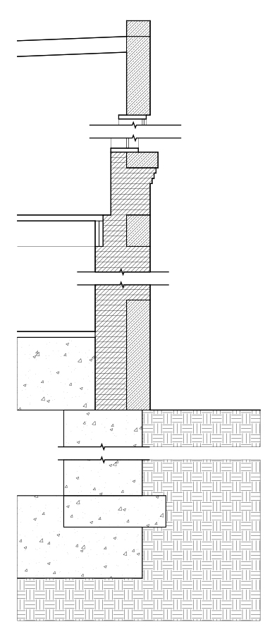
Initially, the line drawing is undifferentiated with respect to lineweight, material notations, dimensions, and hatch patterns:

13.jpg

Step 2. In AutoCAD, define several new layers corresponding to a categorization scheme. For example, different layers could correspond to different materials, or different layers could correspond to different lineweights.

Once you have defined the new layers, assign each of the objects (lines) in the drawing to one of the layers. The image below shows one possible categorization scheme, where the layers represent different materials (e. g., brick and stone):

14a.jpg

Step 3. Add detail lines to the drawing. The image below shows one step in this process, where detail lines are added to represent horizontal joints between successive brick courses.

15a.jpg

Step 4. Continue the process of adding detail lines. In the image below, detail lines are drawn to show “elements beyond” the cutting plane – specifically, lines representing the window jambs and lines representing the bottom edges of floor joists.

16a.jpg

Step 5. Add hatch patterns to materials as appropriate:

17a.jpg

Step 6. Save the AutoCAD drawing in 2007 .dwg format and open it in Illustrator. (This will preserve the layer assignments.) In Illustrator, assign lineweights as appropriate for scale:

18.jpg

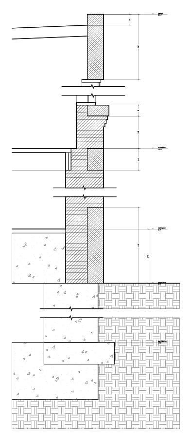
Step 7. Add notes and dimensions as appropriate for scale. (Alternatively, notes and dimensions can be added in AutoCAD and imported to Illustrator with the other information.)

19.jpg


Techniques for Reducing File Size

This page summarizes file-size reduction techniques for several software applications. File-size reduction strategies are usually directed toward managing the overall size of a package of documents.

NOTE: As a general rule, full-size (non-reduced) copies of important documents should always be archived and backed up: reduced-size copies are not usually meant as a replacement for full versions.


REDUCING FILE SIZE IN PHOTOSHOP IMAGES:

MANAGING LAYERS. A reduced-size Photoshop image, regardless of file type, should always be “flattened” into a single layer. Use the Layer > Flatten Image command.

MANAGING IMAGE RESOLUTION. Use the Image > Image Size command to adjust image dimensions and resolution. Images measuring approximately 5” or 6” in their longest dimension, with a resolution of 150 or 200 pixels per inch, usually represent a good balance between file size and image quality.

CHOOSING THE PROPER FILE TYPE. Generally, though not always, the smallest Photoshop files will be met by using the JPEG file type. Use the File > Save As command. Setting the JPEG quality to “Medium” will represent a good balance of size and quality. In the case of images with large areas of solid color, using the TIFF format (with LZW compression) will usually result in a smaller file.


REDUCING FILE SIZE IN ILLUSTRATOR DOCUMENTS:

CHOOSING THE PROPER FILE TYPE. Illustrator uses two different “native” file formats, AI and PDF. To reduce file size, use the File > Save As command to save your Illustrator file in PDF format. When prompted to choose an “Adobe PDF Preset,” choose “Smallest File Size.”

ADDITIONAL OPTIONS. Refer to this site for a detailed description of Illustrator optimization techniques:
http://helpx.adobe.com/illustrator/kb/optimize-native-pdf-file-sizes.html


REDUCING FILE SIZE IN PDF FILES:

COMBINING DOCUMENTS IN ADOBE ACROBAT. If you choose to combine files into a single PDF, click the “Smallest File Size” icon. Use the “Single PDF” rather than the “PDF Portfolio” option.

PRINTING AS THE SMALLEST FILE SIZE. Open a PDF in Acrobat. Choose File > Print. Select PDF as your printer (Adobe PDF or a PDF Writer). Click the “Properties” button. Under “Default Settings,” choose “Smallest File Size.” Click OK, and then click Print.


REDUCING FILE SIZE IN AUTOCAD DRAWINGS AND MODELS:

PURGING THE AUTOCAD DRAWING. AutoCAD drawings often contain unnecessary information (e. g., unused blocks, layers, text styles, etc.). Type PURGE at the command prompt to eliminate such information. Follow the PURGE command with the File > Save As command.

THE OVERKILL COMMAND. Type OVERKILL at the command prompt to delete certain kinds of information in the drawing, e. g., lines which overlap other lines.

FILE > SAVE AS. Use this command to save a new copy of your AutoCAD file. This will usually reduce file size.


REDUCING FILE SIZE IN REVIT MODELS:

PURGING UNUSED ITEMS. Under the Manage tab, Settings panel, choose Purge Unused. This tool will tend to have a greater effect on Projects than Families.

[APPLICATION MENU] > SAVE AS. Use this command to save a new copy of your Revit file. This will usually reduce file size. Test the effect of checking the “Compact File” option while saving (Click Options in the Save As dialog box).


REDUCING FILE SIZE IN RHINO MODELS:

PURGE THE MODEL. Type PURGE at Rhino’s command prompt.

FILE > SAVE AS. Use this command to save a new copy of your Rhino file. This will usually reduce file size.


REDUCING FILE SIZE IN SKETCHUP MODELS:

PURGE UNUSED. Choose Window > Model Info > Statistics; click Purge Unused. Follow this with File > Save As.

ELIMINATE TEXTURES. A copy of your model saved without textures will be much smaller than the same model with textures.

FILE > SAVE AS. Use this command to save a new copy of your SketchUp file. This will usually reduce file size.


Linetypes

CONVENTIONAL USES FOR LINETYPES:

Dashed lines are often used to indicate items above the plan cut or in front of the section cut, or objects below or beyond a visible surface.

A “center” linetype (a repeated pattern of single long dash and single short dash) is usually used to indicate gridlines or center lines of objects or spaces.

Specialty linetypes are often used by various engineering disciplines to indicate utility routes; such linetypes often consist of a dashed or broken line annotated with the service description.

Lineweights

Lineweight is the visual thickness of lines. The use of lineweight is critically important to maintaining good legibility and professional appearance in drawings.

The following pair of drawings of the Robie House in Chicago illustrate conventional uses of lineweights:


robie-plan


LINEWEIGHT CONVENTIONS:

Discerning objects cut by a plane. Relatively heavy lineweights (e. g. in excess of 0.5 mm) are usually used to designate objects cut by a plane. For example, in a plan drawing, a lineweight of 0.5 mm might designate walls and columns; in a section drawing, the same lineweight might designate floors, walls, and the ground.

Discerning changes in observable planes. Relatively medium lineweights (e. g. 0.3 mm or so) are usually used to designate objects observed against a background. For example, in a plan drawing, a lineweight of 0.3 mm might designate a countertop, an item of furniture, stairs, a balcony edge, and so on; in a section or elevation drawing, the same lineweight might designate the outline or edge of a wall against a distant wall, or an opening in a wall. In an axonometric drawing (such as the one of the Robie House to the left), a medium or heavy line might outline solid objects against a background.

Discerning changes in material occurring on a single plane. Relatively thin lineweights (e. g. less than .1 mm) are usually used to designate changes in material occurring on a single plane. For example, in a plan drawing, a lineweight of less than 0.1 mm might designate a threshold at a door, or the spring point of a ramp; in a section or elevation drawing, the same lineweight might designate trim around a door or window.

Designating material or texture. The thinnest possible lineweight (0 mm) is often, though not exclusively, used for hatch patterns in plans, sections, and elevations. Note that 0 mm does not indicate “no line”; rather, it indicates the thinnest line producible by the selected output device.

Step-by-Step: Image Trace in Illustrator

Illustrator’s Object > Image Trace commands are used to automatically trace a raster image, creating vector geometry. These commands are especially useful as a step in constructing digital contour models from scanned topographical maps, and other similar tasks.


AN IMAGE TRACE WORKFLOW:

1.  Open a raster image (e. g., a scan or a photograph) in Photoshop.

2.  Using Photoshop, convert the image to a bitmap figure-ground. You will probably need to experiment with the right combination of options to achieve good results. Try using Photoshop’s Filter > Gaussian Blur command to blur the image before converting it to a bitmap (Image > Mode > Bitmap). When converting the image, the 50% Threshold option will usually give the best results. After converting it, change the image mode to Grayscale, and try blurring it again. (The right combination of commands will depend on the resolution and composition of the image.) Save the bitmap image as a TIF file.

3.  Open or Place the image in Illustrator.

4. Use the Selection tool (the arrow tool) to select the image.

5.  Choose Window > Image Trace. This brings up the Image Trace options panel.

6. In the Image Trace options panel, set the Preset to Line Art.

7. Experiment with other settings (including the Advanced settings) to achieve optimal results, depending again on the resolution and composition of your original image.

8. After completing the trace, click on the resulting object and choose Object > Image Trace > Expand.

9. Copy the resulting object into a new Illustrator file. You can also save it as a .DWG or .DXF file, which you can open, import, or link to Rhino, AutoCAD, SketchUp, or Revit.

Illustrator: Artboards

Every Illustrator document contains one or more rectangular Artboards (up to a maximum of 100 per document). An Illustrator artboard is analogous to a rectangular piece of paper on which artwork is drawn or pasted. It is similar to an AutoCAD Layout space.


STARTING A NEW FILE.

Whenever you use File > New to start a new Illustrator file, you are prompted to select the number of artboards. By default, the value is 1 (one) artboard, but a single Illustrator file can have up to 100 unique artboards. Entering any number greater than 1 will cause Illustrator to prompt you to select a numbering/display order for the artboards.


EDITING ARTBOARDS.

While working on an Illustrator file, you may need to edit (or add or delete) artboards. This can be done at any time by choosing File > Document Setup and clicking on the Edit Artboards button. The resulting interface includes an options bar (top of the screen) with several customizing options as detailed below. (Note that in the case of multiple artboards, each artboard can have unique settings such as size and orientation.)
The Presets box allows you to select from several standard, predefined artboard sizes. (Artboard sizes can also be customized by dragging handles or by entering custom values for the Width and Height settings.)

The Orientation toggle allows you to select the orientation (portrait or landscape) of the selected artboard.

The Name box allows you to specify a unique name for the selected artboard.

The Move/Copy Artwork with Artboard toggle is either on or off, and controls whether Illustrator objects move if the artboard is moved.

Clicking and dragging within the interface creates a new artboard.

Clicking within an artboard selects the artboard.

Clicking the selection tool (the arrow tool) closes the artboard editing interface, saving your changes, and returns you to the basic Illustrator interface.


TO PASTE ARTWORK ON MULTIPLE ARTBOARDS:

1. Select and copy the artwork you wish to paste.

2. Choose Edit > Paste on All Artboards.