Developing a Wall Section in AutoCAD and Illustrator

This tutorial begins with a line drawing extracted from a 3D model of a masonry building. The tutorial shows how the line drawing can be developed in AutoCAD and Illustrator into a presentation-quality drawing.

Step 1. Open a line drawing of a wall section. (In this tutorial, the original line drawing was extracted from a Rhino model. To see this process, refer to the tutorial titled Rhino to AutoCAD Workflow: Cutting a Section.)

Initially, the line drawing is undifferentiated with respect to lineweight, material notations, dimensions, and hatch patterns:

13.jpg

Step 2. In AutoCAD, define several new layers corresponding to a categorization scheme. For example, different layers could correspond to different materials, or different layers could correspond to different lineweights.

Once you have defined the new layers, assign each of the objects (lines) in the drawing to one of the layers. The image below shows one possible categorization scheme, where the layers represent different materials (e. g., brick and stone):

14a.jpg

Step 3. Add detail lines to the drawing. The image below shows one step in this process, where detail lines are added to represent horizontal joints between successive brick courses.

15a.jpg

Step 4. Continue the process of adding detail lines. In the image below, detail lines are drawn to show “elements beyond” the cutting plane – specifically, lines representing the window jambs and lines representing the bottom edges of floor joists.

16a.jpg

Step 5. Add hatch patterns to materials as appropriate:

17a.jpg

Step 6. Save the AutoCAD drawing in 2007 .dwg format and open it in Illustrator. (This will preserve the layer assignments.) In Illustrator, assign lineweights as appropriate for scale:

18.jpg

Step 7. Add notes and dimensions as appropriate for scale. (Alternatively, notes and dimensions can be added in AutoCAD and imported to Illustrator with the other information.)

19.jpg


Rhino to AutoCAD Workflow: Cutting a Section

This workflow is designed to generate a line-drawn building section from a Rhino model for use in AutoCAD. It begins with a complete Rhino model and concludes with the AutoCAD drawing.

Step 1. Open the Rhino model:00.png


Step 2: Create a new layer. Give the layer a name like SECTION and a distinctive color. Make this new layer current.

Step 3: In the SECTION layer, draw a line as a guide for the section cut. This line represents the line along which the section will be cut:01.png

Step 4: Type SECTION [enter]. When prompted to Select objects for sections, type ALL [enter]:02.png

Step 5. When prompted to designate the Start of section, click on one endpoint of the guideline. When prompted to designate the End of section, move the mouse to the far side of the objects being cut. (Make sure ORTHO, F8, is turned on if you want to cut the section parallel with the relevant major axis.)03.png

Step 6. Because SECTION is a drawing command, it generates new geometry. As soon as the SECTION command is complete, the newly drawn geometry is automatically highlighted:04.png

Step 7. With the new geometry highlighted, choose File > Export Selected:05.png

Step 8. Save the exported geometry in the AutoCAD (.dwg) format:06.png

Step 9. Choose the 2004 Polylines option:07.png

Step 10. Start AutoCAD and open the drawing exported from Rhino:08.png

Step 11. If prompted with a warning dialog, choose Continue opening DWG file:09.png

Step 12. When the file is opened, it will appear in a “top down” view, so the section will appear like a single line:10.png

Step 13. Type 3DORBIT [enter] to orbit the model into a 3D view:11.png

Step 14. The geometry needs to be rotated to sit “flat” on the x-y plane. Type ROTATE3D:12.png

Step 15. When prompted to Select objects, type ALL [enter] to select all of the objects in the drawing:13.png

Step 16. In order to rotate the geometry in three-dimensional space, a rotational axis with two endpoints must be defined. Click on a point within the drawing to define the first endpoint of this axis:14.png

Step 17. With Ortho (F8) turned on, click on another point within the drawing to indicate the other endpoint of the rotational axis:15.png

Step 18. When prompted to Specify rotation angle, type either 90 [enter] or -90 [enter] depending on whether the geometry needs to rotate clockwise or counterclockwise around the axis. (To correct a mistaken rotation, the command can be undone or repeated with a rotation angle of 180.)16.png

Step 19. Type PLAN [enter]:18.png

Step 20. When prompted, click [enter] to accept the Current coordinate system (i. e., the World coordinate system):19.png

Step 21. It may be necessary to rotate the geometry again, but only in two-dimensional space. In the case shown here, the geometry needs to be rotated by 90 degrees. Type ROTATE [enter] and indicate the rotation angle:21.png

Step 22. The section drawing is ready. It may also be necessary to use the FLATTEN command to project all geometry to the x-y plane:

23.png


AutoCAD: Working in 3D Space.

Visualizing 3D Space.

Use the View > Views panel to choose between one of several preset orthographic and isometric views of AutoCAD’s simulated three-dimensional space.

Use the VPORTS command to configure multiple model space viewports within model space. This feature lets you view your work from several different directions simultaneously. (Also View > Model Viewports > Viewport Configuration.) [Note: model space viewports operate differently than paper space viewports. Model space viewports are easily configurable to allow simultaneous, dynamic views of a model under construction; Layout space viewports are better suited to a composition of fixed views on a page.]

Use the 3DORBIT command to control the projection by mouse. While in the 3DORBIT interface, right-click to change the projection from parallel to perspective.


Basic 3D operations.

The commands which you have learned in 2D work will also work in 3D. Some of the commands (ROTATE, MIRROR, OFFSET) make reference to the current x-y plane. To change the x-y plane, use the UCS command (discussed below). Tip: Be careful when you use the TRIM, FILLET, and EXTEND commands in 3D. These may not always work the way you expect them to, because of the confusion resulting from representing a 3D space on a 2D screen, and also because they don’t operate on three-dimensional solids.


Building a box.

The BOX command is used to build cubical volumes representing beams, walls, floors, sills, building masses, etc. To build a box:

  1. Type BOX at the Command prompt.
  2. At the prompt Specify corner of box or [CEnter] <0,0,0>, point-click or enter coordinates to specify a corner of the box.
  3. At the prompt Specify corner or [Cube/Length], point-click, enter coordinates, or select the C or L options to continue.
  4. At the prompt Specify height, point-click or enter a number to specify the height.

Related commands: SPHERE; CYLINDER; WEDGE


The UCS command.

Use the UCS command to temporarily change the coordinate system (i. e., the axes along which AutoCAD measures x, y, and z coordinates). UCS is especially useful for 3D work, as planes of reference often change if objects are modeled at different angles or at multiple heights.

The three-point option: To invoke this command, type UCS and then 3. Click on three points in space to define the new axes.

The align to object option: Use the hidden OB option within the UCS command to align the UCS to any visible object.

To return to the normal axes: type UCS and then W.

To generate a plan view with respect to the current coordinate system: type PLAN at the command prompt.


Rotating objects around a point.

Use the ROTATE command as in 2D space. [NOTE: the ROTATE command rotates selected objects around a base point on the x-y plane. To change the current x-y plane, use the UCS command. Or, to rotate selected objects around a line, use the ROTATE3D command.]


Rotating objects around an axis.

To rotate an object around an axis:

  1. Type ROTATE3D at the Command prompt.
  2. Select the objects you wish to rotate.
  3. At the prompt Specify first point on axis or define axis by [Object/Last/View/Xaxis/Yaxis/Zaxis/2points], click on a point on the intended base line (or use one of the other methods; see AutoCAD’s Help for additional information).


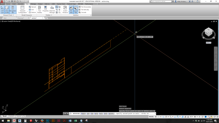
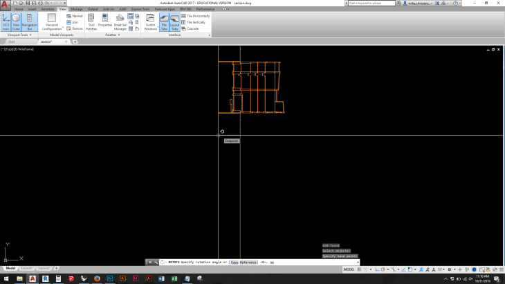
Creating a quick 3D drawing from existing 2D elevations.

  1. View an elevation drawing in three-dimensional space.
  2. Select the lines composing the elevation.
  3. Use the ROTATE3D command to rotate these lines about the “base line” or “ground plane” in the elevation drawing: rotate them by either 90 or -90 degrees (if you choose the wrong one, rotate them again by 180 degrees).

Extruding.

Use the EXTRUDE command to “push/pull” closed polylines (e. g. rectangles) into three-dimensional space to a given height. Tip: EXTRUDE won’t work on blocks or hatches. Tip: Use the PEDIT command to join independent lines and arcs into closed polylines. Use the PEDIT Multiple option, with a fuzz distance set to a number greater than 0, to join lines which don’t meet into a closed polyline.


Slicing.

Use SLICE to cut objects along a plane. This is somewhat analogous to the TRIM command in two dimensions.

Example use of the SLICE command:

  1. Construct a simple rectangular box (e. g. with the BOX command).
  2. Type SLICE at the Command prompt.
  3. Select the box.
  4. Click on three non-colinear points to define a slicing plane: for example, the midpoints of existing sides of the box, or the endpoints of temporary location lines.
  5. Click on a point on the side of the slicing plane corresponding to the portion of the object you wish to keep.

slice


Joining 3D Objects.

The UNION command is used to join two or more 3D objects together in a single object. Together with COPY, it can be used as a three-dimensional equivalent to the EXTEND command: For example, copy a 9-inch-high cube from 0, 0, 0 to 0, 0, 3; UNION the two objects; the result is a new object, 12 inches high.


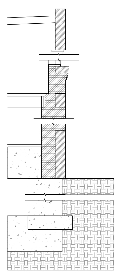
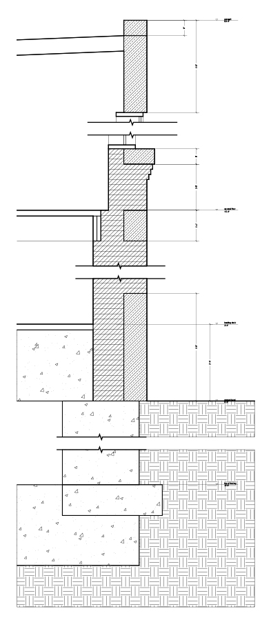
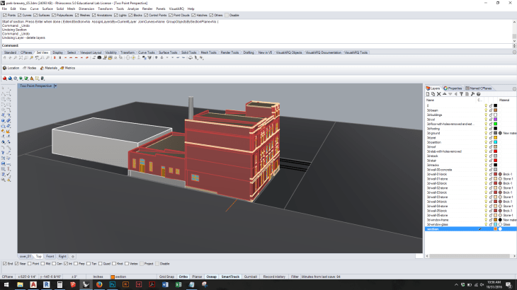
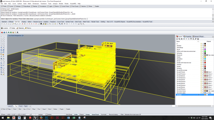
Cutting Plans and Sections.

The SECTION command generates a special kind of AutoCAD object called a region. Regions are similar to closed, filled polylines; they can be extruded into solids or exploded into lines. Type SECTION at the command prompt; the command operates similarly to SLICE, except that it doesn’t require you to designate a point on the “desired side” of the plane. Also, if you want to cut a section or plan at a specific point, it may help to draw a temporary object such as a box to facilitate defining a cutting plane (per step 4 in the procedure below).

  1. Set the current layer to receive newly drawn section information.
  2. Type SECTION at the Command prompt.
  3. Select the objects to cut. (For example, draw a window around the entire model.)
  4. Click on three non-colinear points to define a slicing plane in plan or section. (For example, points on the surface of a box.)
  5. The current layer receives new objects (regions). Turn off all other layers to see these new objects. The objects can be exploded (using the EXPLODE command) to turn them into simple lines.

section


AutoCAD: Plot Style Tables.

A plot style is a set of instructions telling AutoCAD how to print objects. Plot styles can override object settings: for example, a plot style might instruct AutoCAD to print all objects in a drawing using black ink, rather than object/layer colors. A plot style table is a set of plot styles. Plot style tables are assigned to layouts; each layout can have a different plot style table (or no plot style table at all, meaning that no special instructions are used to print the drawing).

Types of plot style tables.

Plot style tables are of two types: color-dependent and named. Color-dependent plot style tables instruct AutoCAD to assign plotting properties based solely on object color. For example, a color-dependent plot style table might instruct AutoCAD to assign every red object in a printout a given line width. Named plot style tables instruct AutoCAD to assign plotting properties to objects independent of their color.

Color-dependent.

Color-dependent plot style tables are primarily useful for one reason: they can be used to assign printed line weights on the basis of color. This is typically how professional offices set up plot style tables, because it is equivalent to the Pen Assignments feature in older versions of AutoCAD.

Named.

Named plot styles allow a greater degree of freedom than color-dependent plot style tables, in the sense that printing properties may be assigned separately from object color. Under this scheme, plot style is an object property, like color or lineweight.

Creating a plot style table.

To create a color-dependent plot style table:

  1. Choose [Application Menu] > Print > Manage Plot Styles.
  2. Double-click on the Add-A-Plot Style Table Wizard icon.
  3. In the introductory dialog box, click Next.
  4. In the “Begin” dialog box, select “Start from scratch” and click Next.
  5. In the “Pick Plot Style Table” dialog box, select “Color-Dependent Plot Style Table” and click Next.
  6. In the “File name” dialog box, enter a name for your plot style (for example, “Style-1”) and click Next.
  7. In the “Add Plot Style Table – Finish” dialog box, click “Finish”. (The next section discusses the detail of editing plot style tables.)

[Note: Plot style tables are stored on the local hard drive and are NOT retained together with your AutoCAD drawing, should you move to a different computer. If you wish to save a plot style table together with your drawing, choose [Application Menu] > Print > Manage Plot Styles; then hold down the Shift key as you drag-and-drop the desired table to an external drive. Invert this process on the second computer. (You are copying a .ctb file between two computers.)]


Editing a plot style table.

To edit a plot style table:

  1. Choose [Application Menu] > Print > Manage Plot Styles.
  2. Double-click on the name of the plot style table you wish to edit.
  3. In the Plot Style Table Editor, you can view information about your table in three separate tabs. To continue with our example, choose the Form View tab. This will display information about your table as a form.
  4. Specify the colors for which you wish to designate printing attributes. (To select every color in the list simultaneously, hold down the SHIFT key as you click on the first and last colors in the list.)
  5. Specify attributes. (For example, under Properties / Color, choose Black.)
  6. Click Save & Close.

Assigning a plot style table to a layout.

Assigning a plot style table to a layout forces AutoCAD to follow the instructions in the table. To assign a plot style table to a layout:

  1. Click on the layout tab to which you wish to assign a specific plot style table.
  2. Type PAGESETUP.
  3. Click Modify.
  4. Under Plot Style Table tab, choose the plot style table you wish to assign to the layout.
  5. Click on the Display plot styles check box.
  6. Click OK.

AutoCAD: The XREF command.

Use the XREF (eXternal Reference) command to reference one drawing into another. The referenced drawing is often called a base drawing or simply an XREF. The concept is essential when you’re organizing a large set of drawings consisting (for example) of floor plans, ceiling plans, sections, title borders, etc.


A typical application.

A typical application of the XREF command involves the creation of “plot sheets.” Plot sheets are AutoCAD drawings which contain an XREF’d base drawing, such as a floor plan, which is viewed through a layout space viewport. Plot sheets also usually contain an XREF of the architect’s title border.


Example use of the XREF command.

  1. Draw a floor plan using standard AutoCAD drawing commands. Save the drawing in an accessible location (e. g., a shared drive). Close the floor plan.
  2. In a second drawing, type XREF. Right-click in the empty area of the panel to reference (“Attach”) the floor plan drawing into the model space of the plot sheet.
  3. In the layout space of the plot sheet, create a scaled viewport through which you can see the floor plan. Use the viewport to manage layers.
  4. Use the XREF command to reference a copy of the architect’s title border into the layout space. (A title border is an AutoCAD drawing containing project-specific information.) Title borders typically contain space for sheet-specific information such as a sheet number and name.

Note: Plot sheets can be composed to show multiple XREFs at multiple scales.


Overlay or Attach?

Every XREF is classified either as being attached or overlaid. Attached XREFs will “nest” into successive XREFs: You can XREF a drawing containing another overlaid XREF. Overlaid XREFs do not nest: if, in a new drawing, you attach an XREF containing an overlaid XREF, the overlaid XREF won’t appear in the new drawing. In the XREF dialog box, double-click on the word Attach (or Overlay) next to the XREF drawing name to change its status.


Common base point.

If you create a series of drawings such as floor plans, elevations, and sections, describing a single building, consider drawing each drawing such that the point (0, 0, 0) represents the same point in space in each drawing. This allows easy cross-checking of (for example) plans to sections by XREFing one into the other at (0, 0). Such cross-checking also works between floor plans – allowing easy verification of whether, for example, elevators, mechanical shafts, and exterior walls align between drawings.


Multiple users.

By default, AutoCAD will prevent other people on a network from opening a drawing if that drawing is XREFerenced into your drawing. If you wish to disable this feature, and allow other users to edit the XREFs, type OP; click on the Open and Save tab; under External References, set Demand Load to “Enabled with copy.”


Binding XREFs.

To “break the link” between an XREF and its host drawing, and to permanently insert the XREF within the host: in the XREF Manager dialog box, highlight an XREF and click Bind. Choosing Insert is equivalent to using the Insert command to copy an external .dwg file into the host drawing. Choosing Bind inserts the XREF into special new layers, intentionally keeping the XREF layers separate from the host drawing layers.

AutoCAD: Applying Dimensions.

To apply dimensions in paper space:

  1. Click on a layout tab. Create a viewport and set its scale as desired. View all or part of the drawing through the viewport.
  2. Use the MV command to lock the viewport. This prevents zooming and panning within the viewport; zooming changes the scale, which throws off the consistent scale of dimensions applied through the viewport.
  3. Apply dimensions using any of the methods described below.

Dimensioning Using the DIM Command.

Type DIM at the command prompt; this invokes a special dimensioning prompt which responds to special commands including HOR (horizontal), VER (vertical), ALIGNED (diagonal), or ORDINATE (i. e., datum level). Generally, these commands apply dimensions by asking you to specify two “extension line origin” points (i. e., the points you are measuring between) and a “dimension line location.” ORDINATE asks for a “feature location” and a “leader endpoint.”


Linear dimensions.

Use the Annotate > Dimension > Linear command (or DIMLINEAR at the command prompt) to apply automatic linear dimension strings to a drawing.


Ordinate dimensions.

Use the Annotate > Dimension > Ordinate command to apply automatic datum elevations to an elevation or section drawing. (Note: To change the datum point, use the UCS command to define a temporary origin point for the coordinate system.)


“Quick Dimensioning” (QDIM and QLEADER).

Use QDIM to quickly apply a series of dimensions to selected objects. Use QLEADER to apply and control settings for leader (arrow) lines.


See also:

AutoCAD: Using Dimensions.

AutoCAD Tutorial: Dimensions. http://www.cadtutor.net/tutorials/autocad/dimensioning.php

AutoCAD: Using Dimensions.

Introduction.

Dimensions are annotations which communicate information about sizes and locations of items within assemblies and structures.

A dimension in AutoCAD is an object consisting of, at a minimum, two points in space and a number indicating the length between these points. The number is created automatically by AutoCAD: a dimension can be thought of as combining the functions of the DIST (distance) command and the TEXT command.

A typical application of dimensions in an AutoCAD drawing is consistent with the following:

1. Dimensions are assigned to a unique layer.

2. Dimensions are formatted to produce uniform text and arrow sizes across multiple drawing scales.


Dimension styles.

Every dimension added to an AutoCAD drawing is subject to the settings of a dimension style. Every drawing has a minimum of one dimension style called Standard. This style can be modified or renamed, but not deleted entirely.

To modify an existing dimension style, type DIMSTYLE (or expand the Annotate> Dimensions panel) to bring up the Dimension Style Manager dialog box. Click on the Modify button. (See comments on style settings below.)

To add a new dimension style, type DIMSTYLE (or expand the Annotate> Dimensions panel) to bring up the Dimension Style Manager dialog box. Click on the New button. Every new style is necessarily based on the settings for an existing style, although these can be modified.

To change drawn dimensions from one style to another style, use either the MA command or the CH command.


Dimension Style Settings.

Use the Modify button in the Dimension Style Manager box to change dimension style settings.

In the Modify Dimension Style dialog box, tabs organize the settings into seven categories:

Lines.   These settings control the appearance of the lines which compose dimension strings: for example, are the extension lines offset from object corners, and to what amount?

Symbols and Arrows.     Arrowheads are chosen from a preset list or are assigned a block from the drawing. To produce consistent results, arrow sizes should be set according to their intended printed size. An arrow size no greater than 1/4” is typical.

Text.     These settings control the appearance of text in dimension strings. Text settings are subject to the settings of the current text style (separately controlled with the STYLE command). For predictable results, text height should be set in a text style as 0 (zero) and in a dimension style according to its intended printed size. Dimension text height no greater than 1/4” is typical.

Fit.        The settings on the Fit tab control (a) the automatic placement of text around dimension strings and (b) the overall scale of dimension features. For ease of use, the dimension features should be set to scale to paper space (but more on this later).

Primary Units.    These settings control the type and format of units in dimension strings. Note that these settings are independent of the settings in the UNITS command.

Alternate Units. These settings allow simultaneous display of (for example) English and Metric units.

Tolerances.       Used primarily in engineering drawings.


Dimensioning in Paper Space.

Consistency of appearance is important for dimensions. The easiest way to produce consistent results is to apply dimensions to your drawing while viewing your work through a paper space viewport. The advantages of this method are:

1. Dimensions are automatically scaled to the viewport scale.

2. The appearance of all dimensions, regardless of their size and scale, is controlled by a single dimension style.

Note: It is also possible, though procedurally more difficult if consistent results are desired, to apply dimensions directly in the model space. This method requires that the dimension features be manually scaled to correspond with the intended printing scale of the drawing (or portion of the drawing): use the overall scale feature on the Fit tab to do this.


See also:

AutoCAD: Applying Dimensions.

AutoCAD Tutorial: Dimensions. http://www.cadtutor.net/tutorials/autocad/dimensioning.php

AutoCAD: Importing and Exporting

TO EXPORT A MODEL OR DRAWING FROM AUTOCAD:

AutoCAD offers a small number of writeable file formats. The most versatile and useful of these are the DWG and DXF formats. Use AutoCAD’s SAVEAS command to export your AutoCAD work in several versions of these formats. (Note, for example, that some software cannot read a 2010 DWG or a 2013 DWG file, so that you may need to SAVEAS a 2007 DWG file to ensure legibilty.)

AutoCAD’s WBLOCK (Write Block) command is useful if you want to export just part of a drawing or model to a new DWG file.

AutoCAD’s EXPORT command is minimally useful: it allows you to export your AutoCAD information in one of a few non-AutoCAD formats.


TO IMPORT A MODEL OR DRAWING TO AUTOCAD:

To get the best results for importing vector information to AutoCAD, the vector information should be previously saved in the DWG or DXF format. Most modeling and drawing software (Rhino, SketchUp, Revit, Illustrator) can write information in one or both of these formats. Use AutoCAD’s File > Open command to open files of either type (DWG or DXF).

AutoCAD also has an IMPORT command which is minimally useful in opening files of non-AutoCAD format.

Edit > Paste can be of use in specific situations when copying and pasting vector information from one document to another.

Techniques for Reducing File Size

This page summarizes file-size reduction techniques for several software applications. File-size reduction strategies are usually directed toward managing the overall size of a package of documents.

NOTE: As a general rule, full-size (non-reduced) copies of important documents should always be archived and backed up: reduced-size copies are not usually meant as a replacement for full versions.


REDUCING FILE SIZE IN PHOTOSHOP IMAGES:

MANAGING LAYERS. A reduced-size Photoshop image, regardless of file type, should always be “flattened” into a single layer. Use the Layer > Flatten Image command.

MANAGING IMAGE RESOLUTION. Use the Image > Image Size command to adjust image dimensions and resolution. Images measuring approximately 5” or 6” in their longest dimension, with a resolution of 150 or 200 pixels per inch, usually represent a good balance between file size and image quality.

CHOOSING THE PROPER FILE TYPE. Generally, though not always, the smallest Photoshop files will be met by using the JPEG file type. Use the File > Save As command. Setting the JPEG quality to “Medium” will represent a good balance of size and quality. In the case of images with large areas of solid color, using the TIFF format (with LZW compression) will usually result in a smaller file.


REDUCING FILE SIZE IN ILLUSTRATOR DOCUMENTS:

CHOOSING THE PROPER FILE TYPE. Illustrator uses two different “native” file formats, AI and PDF. To reduce file size, use the File > Save As command to save your Illustrator file in PDF format. When prompted to choose an “Adobe PDF Preset,” choose “Smallest File Size.”

ADDITIONAL OPTIONS. Refer to this site for a detailed description of Illustrator optimization techniques:
http://helpx.adobe.com/illustrator/kb/optimize-native-pdf-file-sizes.html


REDUCING FILE SIZE IN PDF FILES:

COMBINING DOCUMENTS IN ADOBE ACROBAT. If you choose to combine files into a single PDF, click the “Smallest File Size” icon. Use the “Single PDF” rather than the “PDF Portfolio” option.

PRINTING AS THE SMALLEST FILE SIZE. Open a PDF in Acrobat. Choose File > Print. Select PDF as your printer (Adobe PDF or a PDF Writer). Click the “Properties” button. Under “Default Settings,” choose “Smallest File Size.” Click OK, and then click Print.


REDUCING FILE SIZE IN AUTOCAD DRAWINGS AND MODELS:

PURGING THE AUTOCAD DRAWING. AutoCAD drawings often contain unnecessary information (e. g., unused blocks, layers, text styles, etc.). Type PURGE at the command prompt to eliminate such information. Follow the PURGE command with the File > Save As command.

THE OVERKILL COMMAND. Type OVERKILL at the command prompt to delete certain kinds of information in the drawing, e. g., lines which overlap other lines.

FILE > SAVE AS. Use this command to save a new copy of your AutoCAD file. This will usually reduce file size.


REDUCING FILE SIZE IN REVIT MODELS:

PURGING UNUSED ITEMS. Under the Manage tab, Settings panel, choose Purge Unused. This tool will tend to have a greater effect on Projects than Families.

[APPLICATION MENU] > SAVE AS. Use this command to save a new copy of your Revit file. This will usually reduce file size. Test the effect of checking the “Compact File” option while saving (Click Options in the Save As dialog box).


REDUCING FILE SIZE IN RHINO MODELS:

PURGE THE MODEL. Type PURGE at Rhino’s command prompt.

FILE > SAVE AS. Use this command to save a new copy of your Rhino file. This will usually reduce file size.


REDUCING FILE SIZE IN SKETCHUP MODELS:

PURGE UNUSED. Choose Window > Model Info > Statistics; click Purge Unused. Follow this with File > Save As.

ELIMINATE TEXTURES. A copy of your model saved without textures will be much smaller than the same model with textures.

FILE > SAVE AS. Use this command to save a new copy of your SketchUp file. This will usually reduce file size.


AutoCAD: Inserting, Scaling, and Clipping Images

INSERTING IMAGES: AutoCAD can import Photoshop-readable images, in either the .tif or .jpg format, into drawings for use as backgrounds for tracing, or for applied material textures in 3D models.

Before inserting an image, create and set as current a new layer for images, to preserve the ability to control the image’s visibility separately from other objects in the drawing.

Use the IMAGEATTACH command to bring a Photoshop-readable image into an AutoCAD drawing. In the resulting Image dialog box, specify an insertion point, scale, and rotation, or set these to specify on-screen. Because the image can be moved, scaled, and rotated at any time after being inserted, the entries in the Image dialog box are inconsequential to long-term work.

The DRAWORDER commands prevents images from obscuring other objects in the drawing. However, because AutoCAD rearranges objects following certain commands, it may be necessary to manually reorganize objects repeatedly.


SCALING AN IMAGE: Use the SCALE command to scale an imported image (such as a map or an elevation-oblique image) to its true scale.

1. Type SCALE. When prompted to select objects, select the photograph by clicking on its edge.

2. When prompted to specify a base point, click on any point in the AutoCAD drawing.

3. When prompted to specify a scale factor or [Reference], type R for Reference.

4. When prompted to specify a reference length, click on two points in the image, the distance between which you know.

5. When prompted to specify a new length, type the desired (i. e. the known) length.


scale_reference


CLIPPING AN IMAGE: Use the IMAGECLIP command to clip an image to a rectangle or other polygonal frame.