Creating Grasshopper definitions is rarely a straightforward, linear process. It usually involves having a general idea of what one wants to accomplish, and a sense of which components will be necessary; however, the process almost always involves extensive testing, false starts, discoveries, and iterations along the way.
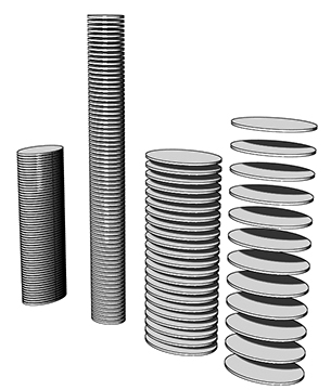
As an example, consider creating a Grasshopper definition which can create elliptical towers:
One way of creating this definition is shown in the following step-by-step procedure.
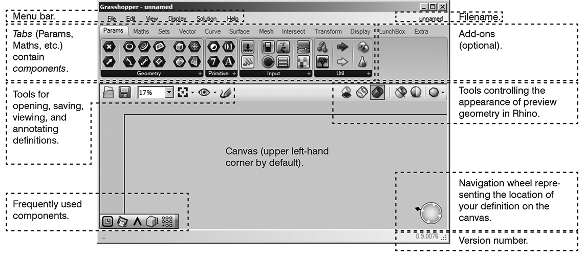
1. Start Rhino; type GRASSHOPPER to start Grasshopper.
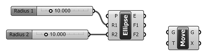
2. Double-click in the Grasshopper canvas to search for and insert the Ellipse component (or Curve > Primitive > Ellipse).
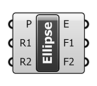
Notice that when the component is placed on the Grasshopper canvas, it is automatically previewed in Rhino, on the basis of its default values:

To see the component’s default values, hover the mouse over the input labels (P, R1, and R2). P, the base plane, is by default the XY plane and is previewed as a red grid in Rhino. R1 and R2, the ellipse’s two radii, are be default both set to one (1.0). Their result is previewed as a red circle in Rhino.
However, we want the component to produce variable-sized ellipses. Therefore, we need to introduce variable input in the form of number sliders.
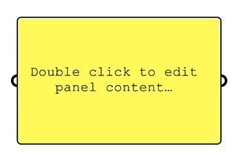
3. Double-click in the Grasshopper canvas to search for and insert the Number slider component (or Params > Input > Number Slider).
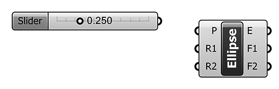
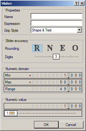
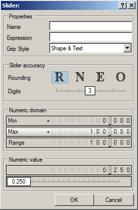
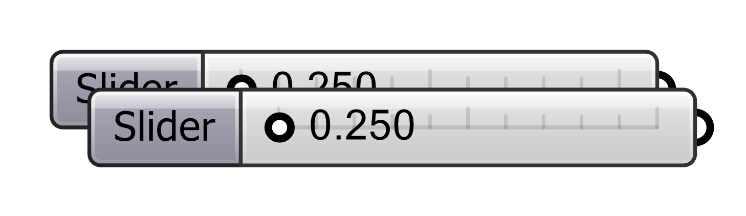
4. Double-click on the label of the number slider (“Slider”) to adjust its values as shown below:
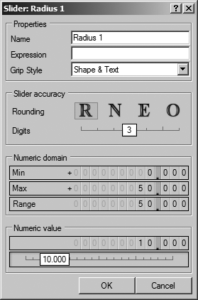
This will allow the slider to generate values between 0 and 50, with a precision rounded to three decimal points. Its initial value is set to 10, but that value is variable.
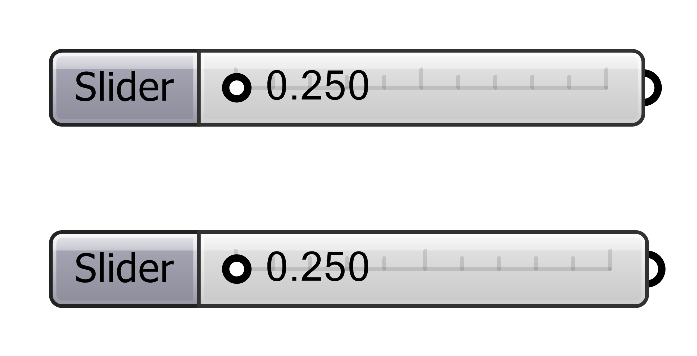
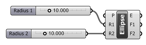
5. Copy and paste the first slider to create another slider. Double-click on this slider and change its name to Radius 2.

6. Connect the two sliders to the Ellipse component by dragging wires between them. Begin by clicking on the slider output node, hold down the mouse button, and release it on the input node of the Ellipse component.
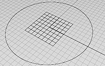
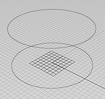
Notice how this affects the Rhino preview:

The ellipse is now shown with radii of 10 units. Adjust the number sliders to see how the preview is affected.
7. Having created a base ellipse of variable size, we now need to begin stacking multiple copies of the ellipse. We’ll do this by copying the ellipse vertically. Grasshopper does not have a Copy component; instead, we use the Move component — with the knowledge that the original ellipse will still preview in its original location.
Double-click in the Grasshopper canvas to search for and insert the Move component (or Transform > Euclidean > Move):

The Move component requires two forms of input, which you can see by hovering the mouse over the input labels (G and T). Input G (Geometry) requires a drawn or modeled object — such as an ellipse. Input T (Motion, or Translate) requires a direction/magnitude in the form of a vector. Notice that by default, input T is set to a vector 10 units long in the Z-direction (0.0,0.0,10.0).
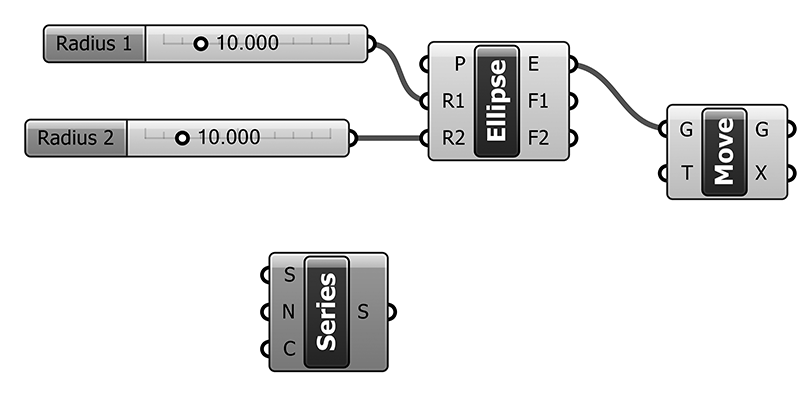
8. Connect the E output on the Ellipse component to the G input on the Move component:

Notice how this affects the Rhino preview:

A new ellipse is previewed 10 units vertically above the original ellipse.
However, we need multiple ellipses, placed at a variable distance (i. e., floor-to-floor height) above the original ellipse. We will need to do something different for the T input on the Move component. Specifically, we will need to provide to this component as input a list of numbers corresponding to the vertical positions of the floors.
9. Double-click in the Grasshopper canvas to search for and insert the Series component (or Sets > Sequence > Series):

The Series component generates a list of numbers according to input parameters. Hover the mouse over the input labels (S, N, and C) to find out what is required for input.
The S input requires a single number, the start of the list. Assuming we want the first floor of our tower to be on the XY plane, S can be set to 0 (zero). The simplest way to do this is to right-click on the S label and choose Set Number from the dropdown menu. (Note that by default, S is already set to zero.)
The N input refers to the step size — the floor-to-floor height. And the C input refers to the count of items in the list — simply, the number of floors in the tower. Both N and C can be controlled with number sliders.
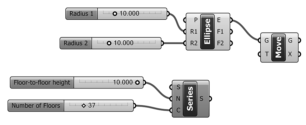
10. Insert two number sliders with the following values (note that Number of Floors is set to Integer rounding):

And then connect the sliders to the Series component as shown below:

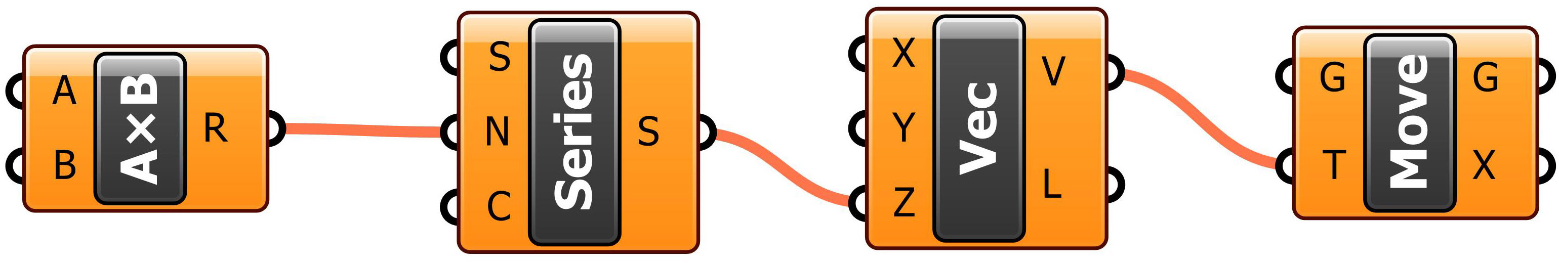
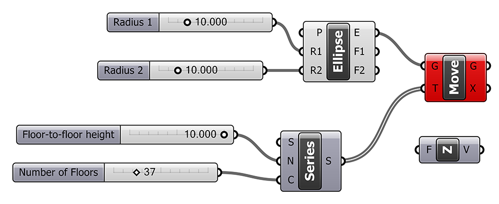
11. Hover the mouse over the S output on the Series component. You should see the list of numbers generated in accordance with the input values. Now, it would seem that we could simply connect the S output from Series to the T input on Move — but if we do this, Grasshopper will generate an error message at the Move component:

The problem is that the Move component expects vectors as input at T; we have given a list of numbers, not vectors. To fix this, we need to insert a Unit Vector component between the Series and Move components.
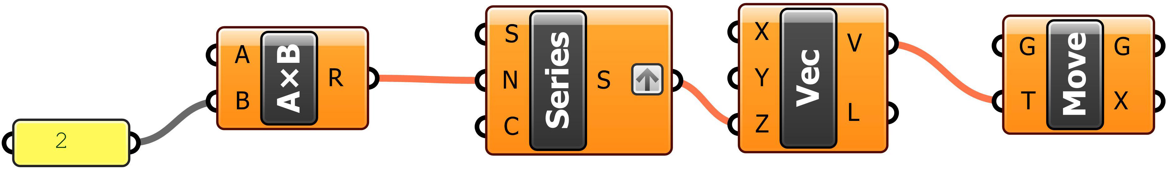
12. Double-click in the Grasshopper canvas to search for and insert the Unit Z component (or Vector > Vector > Unit Z):

13. Reconnect wires as shown below (note: you can manually disconnect wires by right-clicking on input or output nodes and selecting Disconnect):

Once again, notice how this affects the Rhino preview:

Adjust all four number sliders to see the effect on the Rhino preview.
14. That completes the basic definition. Additional steps might include:
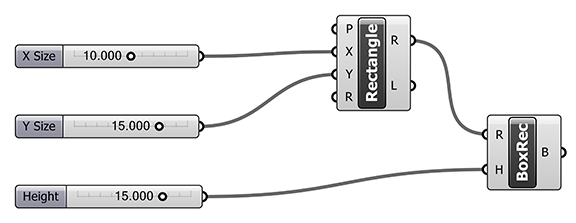
Extruding the floors to a specified or variable thickness (as shown in the image at the beginning of this post);
Varying the elliptical radii along the height of the tower;
Constructing a “skin” on the tower.