This post covers two related concepts: Setting and Editing Properties for Existing Materials and Creating New Materials.
The Material Browser is Revit’s interface for setting the attributes and properties of simulated materials in projects. The Material Browser can be used to specify those attributes for existing materials as well as to create new materials for application within the project.
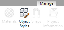
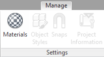
The Material Browser can be accessed directly from Revit’s interface by choosing the Materials tool within the Settings panel of the Manage tab.
The Material Browser provides control over material properties and material assets. Material properties are specific parameters that define the visual and performance characteristics of simulated materials. Material assets are groups of properties.
Revit’s material properties are grouped into four types of material assets:
Graphics assets include the properties for non-rendered display of materials. For example, the color which Revit uses to display a material in the default (non-rendered) 3D view is controlled here.
Appearance assets include the properties for rendered display of materials. For example, a material’s reflectivity and transparency properties are organized into appearance assets.
Physical assets include properties related to a material’s structural performance and behavior. For example, properties such as a material’s yield strength are organized into physical assets.
Thermal assets include properties related to a material’s thermal performance. For example, properties such as a material’s thermal conductivity, density, and permeability are organized into thermal assets.
To Set or Edit Properties for Existing Materials.
1. Open the Material Browser (Manage > Settings > Materials).
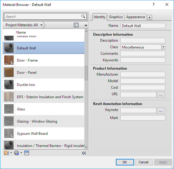
2. Scroll vertically to find the existing material you wish to edit. Click on the material name (for example, “Default Wall”).
3. Click the Identity tab if you wish to edit the material’s Name, Descriptive Information, Product Information, or Annotation Information.
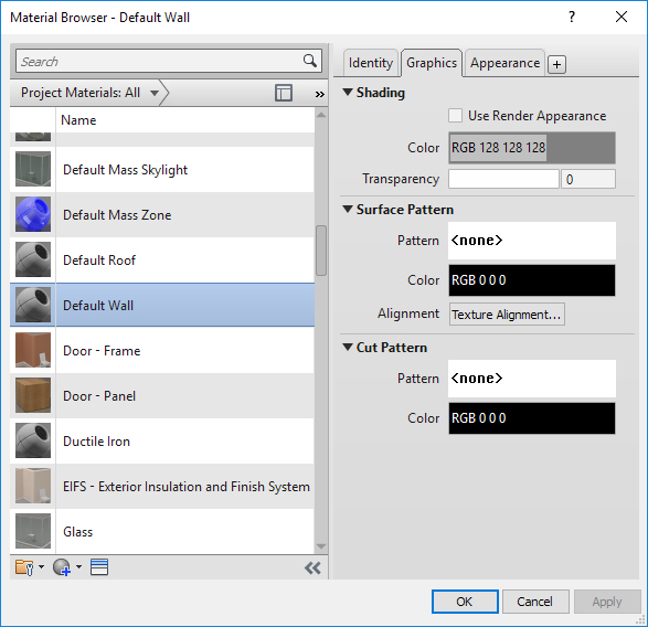
4. Click the Graphics tab if you wish to edit the material’s Shading (its appearance in non-rendered 3D views and elevations), Surface Pattern (the appearance of its outer surface in non-rendered views), or Cut Pattern (its appearance when it is cut in non-rendered views).
5. Click the Appearance tab for full control over the appearance of the material in rendered views.

Generic. The value for Color refers to a base color under neutral lighting. The setting for Image allows you to select an image as a “diffuse color map,” i. e. the underlying image affecting how light is reflected from the material. Image Fade (only available if an Image is selected) controls the relationship between the image and the base color. Glossiness affects how “shiny” or “glossy” the material appears. The dropdown selection for Highlights controls how light is reflected from the material’s surface.

Material rendered without image (left) and with image (right).
Reflectivity. These settings affect how the surrounding environment is reflected in the material’s surface. The reflectivity settings are related to the Generic settings for Glossiness, i. e., glossier materials will tend to perform better as reflecting surfaces.
Transparency. The Amount can be set between 1.0 (100% transparent) and 0.0 (0% transparent, i. e., completely opaque). The Image setting allows an image to be used as a transparency map, and Image Fade controls the opacity of this image. Translucency (available only for nonzero Transparency values) controls the amount of light scattered by the material as the light passes through. Refraction simulates a physical property associated with the extent to which light rays “bend” as they encounter the material surface.

Variations in Refraction. Glass (left) and Water (right).
Cutouts. A cutout is simply a grayscale image which affects the transparency of a material. White pixels in the image render as transparent and black pixels render as opaque. A color image can be used as a cutout, but it is interpreted based on its equivalent grey values.
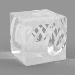
Cutout.
Self Illumination settings are used to make a material appear to glow. However, self-illuminated objects do not cast light onto other objects. (Note: Other rendering software, like 3DS or Maxwell, will allow self-illuminating objects or emitters to cast light onto other objects.)
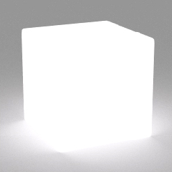
Self Illumination.
Bump. A bump map is an image applied to the surface of a material which has the effect of giving the material a bumpy or irregular appearance. Revit interprets the image according to its grayscale values: black pixels appear lower while white pixels appear higher.

Bump map.
Tint. The tint value changes the appearance of the material’s base color.
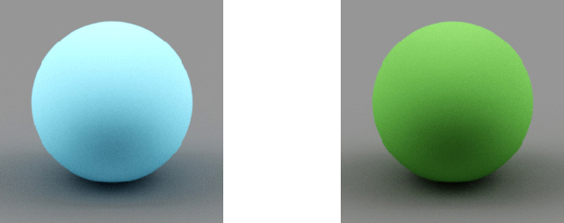
An untinted blue material (left), and the same material with a yellow tint added (right).
To Create a New Material.
1. Open the Material Browser (Manage > Settings > Materials).
2. Click the New Material button at the bottom of the dialog box.
3. Choose either Create New Material (to create a new material entirely from default settings) or Duplicate Selected Material (to create a new material based on existing material settings for a selected material).
4. Modify settings as described above.