This workflow is designed to generate a line-drawn building section from a Rhino model for use in AutoCAD. It begins with a complete Rhino model and concludes with the AutoCAD drawing.
Step 1. Open the Rhino model:
Step 2: Create a new layer. Give the layer a name like SECTION and a distinctive color. Make this new layer current.
Step 3: In the SECTION layer, draw a line as a guide for the section cut. This line represents the line along which the section will be cut: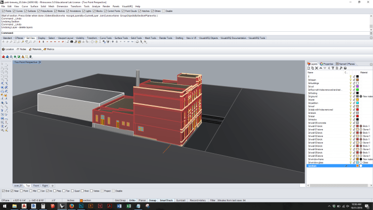
Step 4: Type SECTION [enter]. When prompted to Select objects for sections, type ALL [enter]: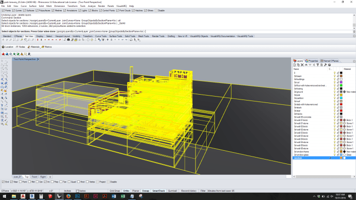
Step 5. When prompted to designate the Start of section, click on one endpoint of the guideline. When prompted to designate the End of section, move the mouse to the far side of the objects being cut. (Make sure ORTHO, F8, is turned on if you want to cut the section parallel with the relevant major axis.)
Step 6. Because SECTION is a drawing command, it generates new geometry. As soon as the SECTION command is complete, the newly drawn geometry is automatically highlighted:
Step 7. With the new geometry highlighted, choose File > Export Selected: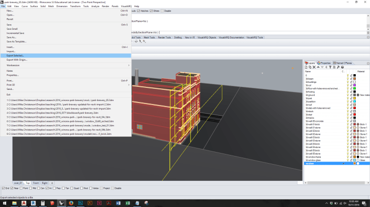
Step 8. Save the exported geometry in the AutoCAD (.dwg) format: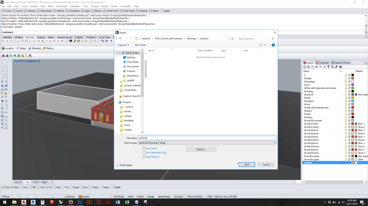
Step 9. Choose the 2004 Polylines option: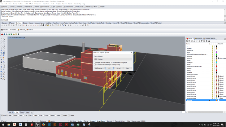
Step 10. Start AutoCAD and open the drawing exported from Rhino: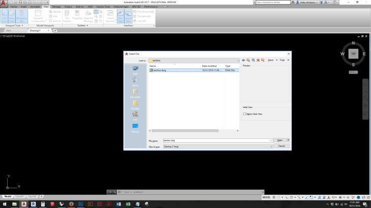
Step 11. If prompted with a warning dialog, choose Continue opening DWG file: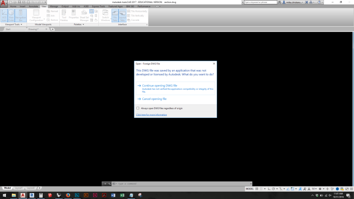
Step 12. When the file is opened, it will appear in a “top down” view, so the section will appear like a single line:
Step 13. Type 3DORBIT [enter] to orbit the model into a 3D view:
Step 14. The geometry needs to be rotated to sit “flat” on the x-y plane. Type ROTATE3D:
Step 15. When prompted to Select objects, type ALL [enter] to select all of the objects in the drawing:
Step 16. In order to rotate the geometry in three-dimensional space, a rotational axis with two endpoints must be defined. Click on a point within the drawing to define the first endpoint of this axis:
Step 17. With Ortho (F8) turned on, click on another point within the drawing to indicate the other endpoint of the rotational axis: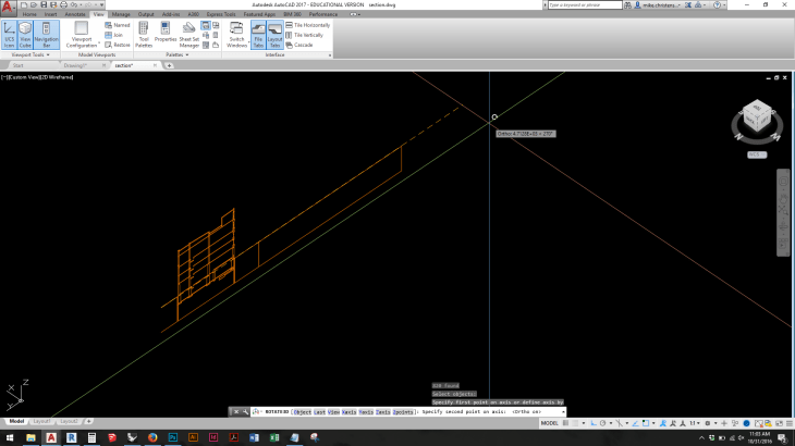
Step 18. When prompted to Specify rotation angle, type either 90 [enter] or -90 [enter] depending on whether the geometry needs to rotate clockwise or counterclockwise around the axis. (To correct a mistaken rotation, the command can be undone or repeated with a rotation angle of 180.)
Step 19. Type PLAN [enter]:
Step 20. When prompted, click [enter] to accept the Current coordinate system (i. e., the World coordinate system):
Step 21. It may be necessary to rotate the geometry again, but only in two-dimensional space. In the case shown here, the geometry needs to be rotated by 90 degrees. Type ROTATE [enter] and indicate the rotation angle: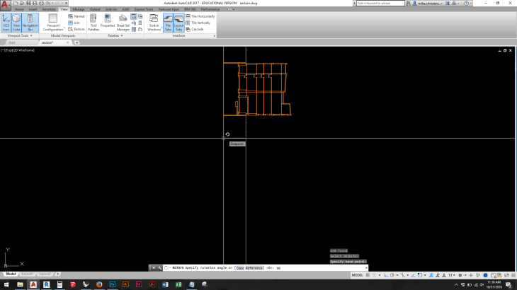
Step 22. The section drawing is ready. It may also be necessary to use the FLATTEN command to project all geometry to the x-y plane:

