Step-by-Step: Building a Model in Revit

revit-tutorial_25-complete

Step 1. Begin a new project.

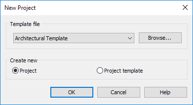
1.1. In the Revit startup screen, under Projects, click on Architectural Template.

Step 2. Set up a Basement Level.

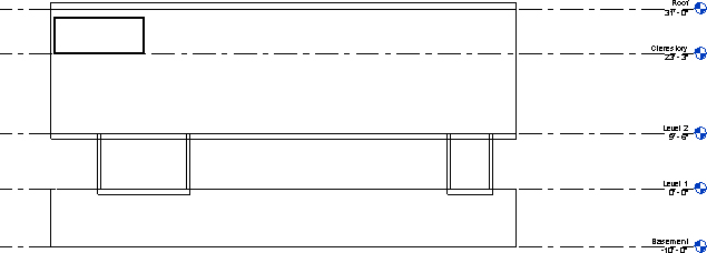
2.1. In the Project Browser, under Elevations (Building Elevation), double-click South.

2.2. Add a Level for the Basement, at an elevation of -10′-0″ (negative ten feet, zero inches).

2.2.1. On the Architecture tab, Datum panel, click on the Level tool. (Keyboard shortcut: LL.)

2.2.2. Position the Level tool at the left end of the already-existing Level 1 line. Don’t click yet; just move the tool downward until the dimension reads 10′-0″ (ten feet, zero inches).

2.2.3. Click to begin the Level.

2.2.4. Move the Level tool to the right until it aligns with the right endpoint of the already-existing Level 1 line.

2.2.5. Click to end the Level. (It will automatically be named Level 3.)

2.2.6. Click [esc] twice.

2.2.7. Double-click on the Level name (“Level 3”).

2.2.8. Type Basement in the text box and press [enter]. When prompted about renaming corresponding views, reply “Yes.”

2.2.9. Click [esc] twice.

Step 3. Modify the existing Level 2.

3.1. Change the elevation of Level 2 to 9′-6″.

3.1.1. Zoom in on the right end of the Level 2 line.

3.1.2. Double-click on the elevation text (10′-0″).

3.1.3. Type 9′-6″ in the text box and press [enter].

3.1.4. Click [esc] twice.

Step 4. Add Levels for the Clerestory and Roof.

4.1. Add a Level for the Clerestory at an elevation of 23′-3″ (twenty-three feet, three inches).

4.1.1. On the Modify tab, Modify panel, click the Copy tool. (By default, the Copy tool has a white circle and two blue circles. Keyboard shortcut: CO.)

4.1.2. Click anywhere on the existing Level 2.

4.1.3. Click [enter].

4.1.4. Click anywhere in the Drawing Area.

4.1.5. Move the mouse vertically, in the upward direction, and type 13′-9″ (thirteen feet, nine inches).

4.1.6. Click [esc] twice.

4.1.7. Rename the newly created Level to Clerestory by double-clicking on the Level name. When prompted about renaming corresponding views, reply “Yes.”

4.2. Using the same process as you used to add the Clerestory Level, add a Level for the Roof at an elevation of 31′-0″ (thirty-one feet, zero inches). (Tip: The Roof Level is 7′-9″ above the Clerestory Level.)

4.2.1. Rename the newly created Level to Roof by double-clicking on the Level name. When prompted about renaming corresponding views, reply “Yes.”

revit-tutorial_01-levels

Step 5. Add walls on Level 2.

5.1. In the Project Browser, double-click on Floor Plans – Level 2.

5.2. On the Architecture tab, Build panel, click the Wall tool. (Tip: Either click directly on the Wall tool icon, or choose Wall: Architectural from the dropdown.)

5.3. In the Options Bar, change the wall height from Unconnected to Roof. (Alternatively, in the Properties Palette, set the Top Constraint to “Up to level: Roof”.)

revit-tutorial_02-options-bar

5.4. In the Properties Palette, set the Type Selector to Basic Wall Generic – 8″.

5.5. In the Modify | Place Wall tab, click the Rectangle tool.

5.6. Use the Rectangle tool to construct a rectangular enclosure measuring 26′-2″ x 80′-0″, dimensioned to the Exterior Finish Face of the walls.

5.6.1. The Rectangle tool can be used to quickly sketch a rectnagular enclosure of approximately correct size; click on two corner points to draw. After the enclosure is sketched, use the temporary dimensions to adjust its size precisely. (Tip: After drawing the rectangle, click on the blue-filled circle at each of the dimension “witness lines” to change the measuring location for a dimension, then click on the dimension text to change the dimension.)

5.7. Click [esc] twice.

Step 6. Construct a Floor on Level 2.

6.1. On the Architecture tab, Build panel, click the Floor tool. (Tip: Either click directly on the Floor tool icon, or choose Floor: Architectural from the dropdown.)

6.2. Use the Floor tool to construct a Floor aligning with the Level 2 walls.

6.2.1. On the Modify | Create Floor Boundary tab, Draw panel, click the Pick Walls tool (it is selected by default).

6.2.2. Use the Pick Walls tool to click in turn on all four walls.

6.2.3. On the Modify | Create Floor Boundary tab, Mode panel, click the green check mark to complete the floor boundary.

6.3. Click [esc] twice.

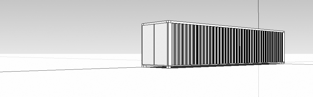
6.4. Optional: At any point in the process, you can view your work in 3D by clicking on the Default 3D View tool in the Quick Access Toolbar.

revit-tutorial_03-default-3d-view

Step 7. Construct Level 1 walls.

7.1. In the Project Browser, double-click on the Level 1 floor plan.

7.2. In the Properties Palette, set Level 2 as underlay.

7.2.1. Click [esc] twice to make sure that nothing is selected. Then, in the Properties Palette, scroll down to the Underlay heading. Set the Range: Base Level to Level 2 and click Apply.

revit-tutorial_04-underlay

7.3. On the Architecture tab, Build panel, click the Wall tool. (Tip: Either click directly on the Wall tool icon, or choose Wall: Architectural from the dropdown.)

7.4. In the Options Bar, set the wall height to Level 2. (Alternatively, in the Properties Palette, set the Top Constraint to “Up to level: Level 2”.)

7.5. In the Modify | Place Wall tab, click the Line tool.

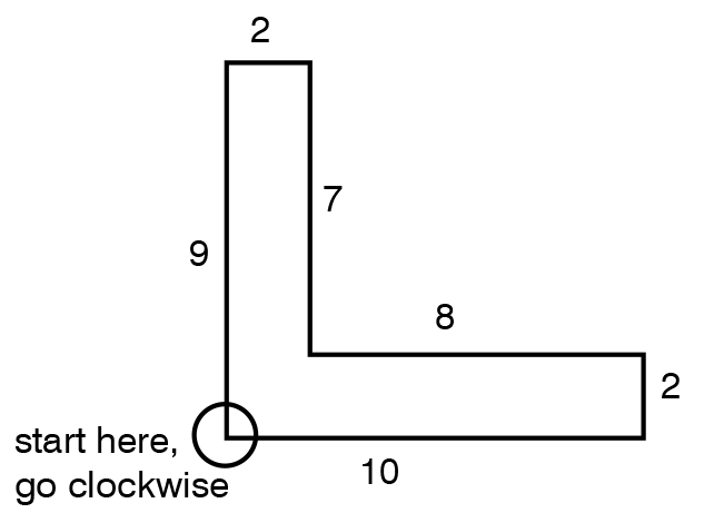
7.6. Use the Line tool to sketch four walls in the north-south direction corresponding to the diagram in the project handout. (Tip: To sketch a wall with the Line tool, hover the mouse over the existing Level 2 wall and click on a Nearest point; then move the mouse downward to the opposite wall and click on a Vertical and Nearest point. Click [esc] and repeat with the next wall. Click [esc] twice to drop the Wall tool.)

revit-tutorial_05-level-1-walls

7.7. Use Temporary Dimensions to precisely set the walls in their desired locations.

7.7.1. Because the project sketch does not indicate dimensions to position the Level 1 walls, you can determine these dimensions on your own. The dimensions in the following steps are shown as an example.

7.7.2. Click [esc] twice to make sure nothing is selected.

7.7.3. Click in succession on two adjacent Level 1 walls to highlight the Temporary Dimensions between them.

7.7.4. Click on the blue-filled circle at each of the dimension “witness lines” to change the measuring location for a dimension. Next, click on the dimension text to change the dimension.

7.7.5. Optional: Click on the Permanent Dimension icon (it is directly beneath the Temporary Dimension text) to display the dimension permanently. Next, click on the permanent dimension, and click on the padlock icon to lock the dimensional relationship.

7.7.6. Optional: Use the Aligned Dimension tool on the Quick Access Toolbar (Keyboard shortcut: DI) to add dimensions anywhere in the project.

revit-tutorial_05-level-1-dimensions

Step 8. Construct Level 1 floor.

8.1. On the Architecture tab, Build panel, click the Floor tool. (Tip: Either click directly on the Floor tool icon, or choose Floor: Architectural from the dropdown.)

8.2. Use the Floor tool to construct two separate floors corresponding to the wall locations.

8.2.1. On the Modify | Create Floor Boundary tab, Draw panel, click the Rectangle tool.

8.2.2. Use the Rectangle tool to draw rectangles corresponding to the two floor locations.

8.2.3. Optional: After drawing a rectangle, click the padlock icon to lock the edge of the floor to the wall.

8.2.4. On the Modify | Create Floor Boundary tab, Mode panel, click the green check mark to complete the floor boundary.

8.3. Click [esc] twice.

revit-tutorial_06-default-3d-view

Step 9. Construct basement walls and floor.

9.1. In the Project Browser, double-click on the Basement floor plan.

9.2. In the Properties Palette, set Level 2 as underlay.

9.2.1. Click [esc] twice to make sure that nothing is selected. Then, in the Properties Palette, scroll down to the Underlay heading. Set the Range: Base Level to Level 2 and click Apply.

9.3. Use the Wall tool to construct perimeter walls at the Basement level.

9.3.1. On the Architecture tab, Build panel, click the Wall tool. (Tip: Either click directly on the Wall tool icon, or choose Wall: Architectural from the dropdown.)

9.3.2. In the Options Bar, set the wall height to Level 1. (Alternatively, in the Properties Palette, set the Top Constraint to “Up to level: Level 1″.)

9.3.3. In the Properties Palette, set the Type Selector to Basic Wall Generic – 12”.

9.3.4. In the Modify | Place Wall tab, click the Rectangle tool.

9.3.5. In the Options Bar, set the Location Line to Finish Face: Exterior.

9.3.6. Click on two opposite corners of the rectangle, corresponding with the Level 2 walls, to create the basement walls.

9.3.7. Click [esc] twice.

revit-tutorial_07-default-3d-view

9.4. Construct the basement floor.

9.4.1. On the Architecture tab, Build panel, click the Floor tool. (Tip: Either click directly on the Floor tool icon, or choose Floor: Architectural from the dropdown.)

9.4.2. On the Properties Palette, use the Type Selector to choose the Generic – 12″ floor.

9.4.3. On the Modify | Create Floor Boundary tab, Draw panel, click the Pick Walls tool(it is selected by default).

9.4.4. Use the Pick Walls tool to click in turn on all four walls.

9.4.5. On the Modify | Create Floor Boundary tab, Mode panel, click the green check mark to complete the floor boundary.

Step 10. Construct the Roof.

10.1. In the Project Browser, double-click on the Roof floor plan.

10.2. In the Properties Palette, set Level 2 as underlay.

10.2.1. Make sure that nothing is selected. Then, in the Properties Palette, scroll down to the Underlay heading. Set the Range: Base Level to Level 2 and click Apply.

10.3. On the Architecture tab, Build panel, click the Roof by Footprint tool.

10.4. Use the Roof by Footprint tool to construct a flat roof.

10.4.1. In the Options Bar, make sure to check “off” on the Defines Slope box before creating the roof.

revit-tutorial_08-options-bar

10.4.2. In the Modify | Create Roof Footprint tab, Draw panel, click the Pick Walls tool (it is selected by default).

10.4.3. Use the Pick Walls tool to click in turn on all four walls.

10.4.4. On the Modify | Create Roof Boundary tab, Mode panel, click the green check mark to complete the roof boundary.

10.5. Click [esc] twice.

revit-tutorial_09-default-3d-view

Step 11. Construct the South Elevation Clerestory Windows.

11.1. Double-click on the South Elevation view.

11.2. On the Architecture tab, Build panel, click the Window tool.

11.3. In the Properties Palette, use the Type Selector to choose the Fixed 36″ x 48″ window.

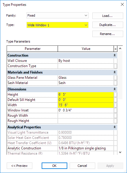
11.4. Click Edit Type.

11.5. In the Type Properties dialog box, click the Duplicate button (upper right-hand corner of the dialog box).

11.6. In the Name dialog box, type Wide Window 1, and click OK.

11.7. In the Dimensions section of the Type Properties dialog box, change the Height to 6′-5″ (six feet, five inches); change the Width to 15′-6″ (fifteen feet, six inches); and change the Default Sill Height to 0′-0″ (zero feet, zero inches).

revit-tutorial_10-type-properties
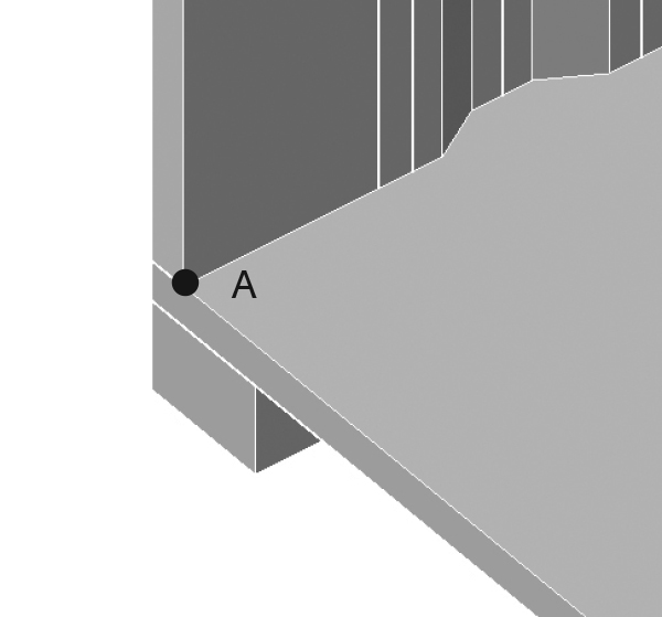
11.8. In the South Elevation view, move the mouse to the clerestory and click to place a window.

revit-tutorial_11-window-south-elevation

11.9. Click to place additional windows; press [esc] twice to drop the Window tool.

revit-tutorial_12-window-south-elevation

11.10. Optional: Fine-tune the placement of the windows using dimension tools.

11.10.1. Double-click on the Clerestory Floor Plan.

11.10.2. Zoom in on the left end of the window on the left end of the wall.

11.10.3. In the View Control Bar (bottom of the screen), set the view scale to 3″ = 1′-0″. (This has the effect of increasing the fineness of lines in the view.)

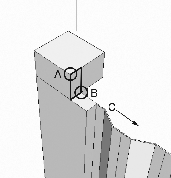
11.10.4. Use the Move tool (keyboard shortcut: MV) to position the window to align precisely with the interior surface of the perendicular wall.

11.10.5. Type ZE to zoom to the extents of the project.

11.10.6. Zoom in on the right end of the window on the right end of the wall.

11.10.7. Use the Move tool (keyboard shortcut: MV) to position the window to align precisely with the interior surface of the perendicular wall.

revit-tutorial_13-window-detail

11.10.8. Type ZE to zoom to the extents of the project.

11.10.9. In the View Control Bar (bottom of the screen), set the view scale to 1/8″ = 1′-0″.

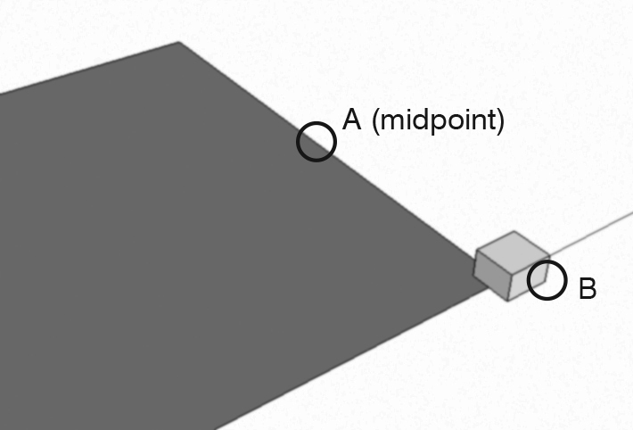
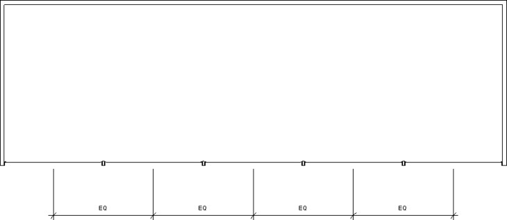
11.10.10. Use the Aligned Dimension tool (keyboard shortcut: DI) to place dimensions measuring between the midpoints of the windows.

revit-tutorial_14-dimensions-unequal

11.11.11. Click the EQ symbol. The dimensions are equalized.

revit-tutorial_14-dimensions-equal

Step 12. Construct the East Elevation Clerestory Windows.

12.1. Double-click on the East Elevation view.

12.2. On the Architecture tab, Build panel, click the Window tool.

12.3. In the Properties Palette, use the Type Selector to choose the Wide Window 1 window.

12.4. Click Edit Type.

12.5. In the Type Properties dialog box, click the Duplicate button (upper right-hand corner of the dialog box).

12.6. In the Name dialog box, type Wide Window 2, and click OK.

12.7. In the Dimensions section of the Type Properties dialog box, change the Height to 6′-5″ (six feet, five inches); change the Width to 12′-3″ (twelve feet, three inches); and change the Default Sill Height to 0′-0″ (zero feet, zero inches).

12.8. In the East Elevation view, move the mouse to the clerestory and click to place a window.

12.9. Click to place additional windows; press [esc] twice to drop the Window tool.

12.10. Optional: Fine-tune the placement of the windows using dimension tools.

Step 13. Mirror the windows to opposite elevations.

13.1. Double-click on the Clerestory Floor Plan.

13.2. In the View Control Bar (bottom of the screen), set the view scale to 1/8″ = 1′-0″.

13.3. Type ZE to zoom to the project extents.

13.4. Select the windows on the south wall.

13.4.1. You can select the windows either by clicking on them one-at-a-time while pressing Ctrl. Or, you can draw a selection window around all of them at once, but then you will need to go to the Modify | Multi-Select tab, Selection panel, and click the Filter tool; check “off” on Walls.

13.5. With the windows selected, in the Modify | Windows tab, Modify panel, click the Mirror – Draw Axis tool (keyboard shortcut: DM).

13.6. Move the Mirror – Draw Axis tool to the midpoint of the west wall. When the midpoint is highlighted, click.

revit-tutorial_15-mirror

13.7. Move the Mirror – Draw Axis tool to the right to indicate a horizontal mirroring line. Click to complete.

13.8. Repeat the mirroring process with the windows on the east wall.

revit-tutorial_16-default-3d-view

Step 14. Expand or redraw the existing Level 1 floor to receive the stair.

14.1.1. Double-click on the Level 1 Floor Plan.

14.1.2. Click on the existing Level 1 floor to select it.

14.1.3. On the Modify | Floors tab, Mode panel, click the Edit Boundary tool.

14.1.4. Use the Draw tools (Modify | Floors > Edit Boundary tab, Draw panel) to adjust the boundary of the floor. Alternatively, the existing floor boundary can be erased and redrawn.

revit-tutorial_17-floor-boundary-before

revit-tutorial_18-floor-boundary-after.jpg

14.1.5. On the Modify | Edit Boundary tab, Mode panel, click the green check mark to complete the floor boundary. If prompted with “Would you like walls that go up to this floor’s level to attach to its bottom?” reply “No.”

Step 15. Construct the Stair from Level 1 to Level 2.

15.1. Double-click on the Level 1 floor plan.

15.2. Click [esc] twice to make sure nothing is selected.

15.3. On the Architecture tab, Circulation panel, choose the Stair by Sketch tool (from the Stair tool dropdown menu).

15.4. In the Properties Palette, check the parameters for the stair. The Base Level should be set to Level 1 and the Top Level to Level 2. Optional: Other stair-specific data can be changed using other parameters within the Properties Palette.

15.5. Click on a point within the stair hall (leftmost space on the first floor) to begin the stair.

15.6. As you move the mouse vertically within the stair hall, Revit will report the number of risers created and the number of risers remaining. (These numbers are determined by the stair parameters in the Properties Palette.)

revit-tutorial_19-stair

15.7. Continue to move the mouse vertically, past the point where the number of risers remaining is 0 (zero). Click to complete the stair.

15.8. On the Modify | Create Stairs Sketch tab, Mode panel, click the green check mark to complete the stair.

15.9. Click [esc] twice.

Step 16. Create a floor opening in Level 2 for the stair.

16.1. Double-click on the Level 2 floor plan.

16.2. On the View Control bar, change the Visual Style to Wireframe. (The Visual Style is set with the icon that looks like a solid cube.) This has the effect of making the floor transparent, so that the stair leading up to this level can be seen.

16.3. Select the existing Level 2 floor.

16.3.1. One way to select the existing floor is to draw a selection window around the entire building, then use the Selection Filter (Modify | Multi-Select tab, Selection panel) to check “off” on everything which is not a floor.

16.4. On the Modify | Floors tab, Mode panel, click the Edit Boundary tool.

16.5. Use the Draw tools (Modify | Floors > Edit Boundary tab, Draw panel) to create a rectangular floor opening at the stair.

revit-tutorial_20-floor-opening

16.5.1. Optional: Use the padlock icons to lock the floor opening edges to the stair.

16.6. On the Modify | Edit Boundary tab, Mode panel, click the green check mark to complete the floor boundary. If prompted with “Would you like walls that go up to this floor’s level to attach to its bottom?” reply “No.”

revit-tutorial_21-stair

Step 17. Construct the Stair from the Basement to Level 1.

17.1. This process is similar to the process for constructing the stair from Level 1 to Level 2. Refer to that process for detail.

Step 18. Create a floor opening in Level 1 for the stair.

18.1. This process is similar to the process for creating a floor opening in Level 2. Refer to that process for detail.

revit-tutorial_22-stair

Step 19. Create a Toposurface around the building.

19.1. Double-click on the Site Floor Plan.

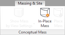
19.2. On the Massing & Site tab, Model Site panel, click the Toposurface tool.

19.3. On the Options Bar, set the Elevation to -6″ (negative six inches).

revit-tutorial_23-options-bar

19.4. In the drawing area, click on a succession of points to establish a rough rectangular boundary around the building.

revit-tutorial_24-site

19.5. On the Modify | Edit Surface tab, Surface panel, click the green check mark to complete the toposurface.

Step 20. Create a Building Pad.

20.1. Double-click on the Site Floor Plan.

20.2. On the Massing & Site tab, Modify Site panel, click the Building Pad tool.

20.3. In the Properties Palette, set the Level to Basement.

20.4. On the Modify | Create Pad Boundary tab, Draw panel, click the Rectangle tool.

20.5. Use the Rectangle tool to trace the outline of the building. Optional: Use the padlock tools to lock the Building Pad edges to the building.

20.6. On the Modify | Create Pad Boundary tab, Mode panel, click the green check mark.

The model is complete.

revit-tutorial_25-complete.jpg

Rhino to AutoCAD Workflow: Cutting a Section

This workflow is designed to generate a line-drawn building section from a Rhino model for use in AutoCAD. It begins with a complete Rhino model and concludes with the AutoCAD drawing.

Step 1. Open the Rhino model:00.png


Step 2: Create a new layer. Give the layer a name like SECTION and a distinctive color. Make this new layer current.

Step 3: In the SECTION layer, draw a line as a guide for the section cut. This line represents the line along which the section will be cut:01.png

Step 4: Type SECTION [enter]. When prompted to Select objects for sections, type ALL [enter]:02.png

Step 5. When prompted to designate the Start of section, click on one endpoint of the guideline. When prompted to designate the End of section, move the mouse to the far side of the objects being cut. (Make sure ORTHO, F8, is turned on if you want to cut the section parallel with the relevant major axis.)03.png

Step 6. Because SECTION is a drawing command, it generates new geometry. As soon as the SECTION command is complete, the newly drawn geometry is automatically highlighted:04.png

Step 7. With the new geometry highlighted, choose File > Export Selected:05.png

Step 8. Save the exported geometry in the AutoCAD (.dwg) format:06.png

Step 9. Choose the 2004 Polylines option:07.png

Step 10. Start AutoCAD and open the drawing exported from Rhino:08.png

Step 11. If prompted with a warning dialog, choose Continue opening DWG file:09.png

Step 12. When the file is opened, it will appear in a “top down” view, so the section will appear like a single line:10.png

Step 13. Type 3DORBIT [enter] to orbit the model into a 3D view:11.png

Step 14. The geometry needs to be rotated to sit “flat” on the x-y plane. Type ROTATE3D:12.png

Step 15. When prompted to Select objects, type ALL [enter] to select all of the objects in the drawing:13.png

Step 16. In order to rotate the geometry in three-dimensional space, a rotational axis with two endpoints must be defined. Click on a point within the drawing to define the first endpoint of this axis:14.png

Step 17. With Ortho (F8) turned on, click on another point within the drawing to indicate the other endpoint of the rotational axis:15.png

Step 18. When prompted to Specify rotation angle, type either 90 [enter] or -90 [enter] depending on whether the geometry needs to rotate clockwise or counterclockwise around the axis. (To correct a mistaken rotation, the command can be undone or repeated with a rotation angle of 180.)16.png

Step 19. Type PLAN [enter]:18.png

Step 20. When prompted, click [enter] to accept the Current coordinate system (i. e., the World coordinate system):19.png

Step 21. It may be necessary to rotate the geometry again, but only in two-dimensional space. In the case shown here, the geometry needs to be rotated by 90 degrees. Type ROTATE [enter] and indicate the rotation angle:21.png

Step 22. The section drawing is ready. It may also be necessary to use the FLATTEN command to project all geometry to the x-y plane:

23.png


Modeling from Mass Instances

This workflow is concerned with the creation of Revit geometry (building elements), such as floors and walls, based on imported masses. (For an example of importing a mass, see Importing a SketchUp Massing Model to Revit.)

1. Create or load a Mass family into a Revit project.

revit_01_05

2. View the mass in an Elevation view.

3. Create Levels corresponding to floor surfaces.

revit_01_07.jpg

4. Return to the default 3D view and select the mass by clicking on it.

revit_01_08.jpg

5. On the Modify|Mass tab, Model panel, click the Mass Floors tool.

revit_01_09

6. Select the Levels corresponding to the Mass Floors you wish to construct. Click OK.

revit_01_10.jpg

7. Verify the placement of the Mass Floors in the default 3D view. (Note: You may need to adjust the Visibility/Graphics settings to see the mass and the floors. Type VG and make sure the Mass category is fully visible.)

revit_01_11.jpg

8. On the Massing & Site tab, Model by Face panel, click the Floor tool.

revit_01_12.jpg

9. On the Modify|Place Floor by Face tab, Multiple Selection panel, click the Select Multiple tool.

revit_01_13

10. Click on a Mass Floor for which you wish to create a building floor. (Note: If the floor is to be offset from the level of its corresponding Mass Floor, set the Offset value on the Options Bar.)

11. In the Properties Palette, choose a Floor Type for the floor you wish to create.

revit_01_14.jpg

12. On the Modify|Place Floor by Face tab, Multiple Selection panel, click Create Floor.

13. Check the placement of floors in the default 3D view. (Note: You may need to adjust the Visibility/Graphics settings in order to hide the mass elements. Type VG and make sure the Mass category is hidden, i. e., unchecked.)

revit_01_15.jpg

Importing a SketchUp Massing Model to Revit

This workflow is intended for the situation in which you have created a massing model in SketchUp and wish to use the model as a guide for the construction of detailed Revit geometry. For the purposes of this tutorial, a massing model is understood to mean a model without interior volumes (corresponding to rooms) and without openings (corresponding to windows and doors).

1. Create a massing model in SketchUp.

2. Save the SketchUp model in .skp format. IMPORTANT: When saving from SketchUp, make sure to use SketchUp Version 8 to ensure compatibility with Revit.

revit_01_04

3. Start a new Revit project, or open an existing project in which you wish to place the massing model.

4. On the Massing & Site tab, Conceptual Mass panel, click the In-Place Mass tool.

revit_01_00

5. If the “Show Mass Enabled” dialog box appears, click Close. (This box appears to notify you that Revit has automatically enabled the display of mass elements.)

revit_01_01

6. Give the mass a name and click OK.

revit_01_02

7. On the Insert tab, Import panel, click the Import CAD tool.

revit_01_03.jpg

8. In the Import CAD Formats dialog box, navigate to your SketchUp file. Accept the default settings, and click Open.

9. Check the default 3D view of your imported massing model.

revit_01_05.jpg

10. Check the overall dimensions of the imported massing model to verify correct scaling. (If the model has imported at the incorrect size, it may be necessary to return to SketchUp to correct the model size and then repeat the importing procedure. Alternatively, it may be necessary to check the settings in Revit’s Import CAD Formats dialog box. Make sure that the Import units are at the default setting of “Auto-Detect.”)

11. On the Insert tab, In-Place Editor panel, click Finish Mass to complete the importing process.

revit_01_06

12. The massing model is now available in the Revit drawing window for further development.

Step-by-Step: Revit Tutorial / Adding Windows and Doors

To use this step-by-step tutorial, you will need to begin with an existing Revit model containing at least one wall.

WINDOWS

1. Choose a window type. On the Ribbon: Architecture > Build > Window. In the Properties palette, choose an appropriate window type (e. g., Fixed 36″ x 48″).

2. Navigate and place. In either a 3D view or a floor plan view of your model, navigate the mouse over the model and click to place a window. Window locations can be modified after placement by clicking on dimension strings and editing them. Windows can also be moved using the Move tool (Modify > Modify > Move, or type MV).


Notes:

To Create a Custom Window Size: On the Ribbon: Architecture > Build > Window. In the Properties palette, choose an appropriate window type (e. g., Fixed 36″ x 48″). In the Properties palette, click Edit Type. In the Type Properties dialog box, click Duplicate. Give the new window type a name (such as Custom — 72″ x 80″). Under Type Parameters, edit the Height and Width dimensions as required. Click OK to exit the Type Properties dialog box.

To Load Additional Window Families: On the Ribbon: Insert > Load from Library > Load Family. In the Load Family dialog box, navigate to the Windows directory and double-click on the family you wish to load. The next time you choose Window from the Architecture > Build panel, the newly loaded family will be available in the Type Selector.


DOORS

1. To Add Doors. Note that the process for inserting Doors is very similar to the process for Windows. Start with Architecture > Build > Door and selecting the desired door type in the Properties Palette. Doors can be placed in different views (e. g. floor plan views or 3D views).

Step-by-Step: Revit Tutorial / Adding Stairs

To use this step-by-step tutorial, you’ll need an existing Revit model containing at least two floor levels.

1. Insert Stairs. In the Project Browser, double-click on the Floor Plan view corresponding to the lower of two floors you wish to join with a stair. On the Ribbon: Architecture > Circulation > Stair (Stair by Component). Next, on the Ribbon: Modify | Create Stair > Components, choose Run, and then click in the floor plan to begin the stair.

2. To create a single-run stair: move the mouse in the direction of the stair run until Revit reads “0 remaining” risers. Click to complete the stair. Finally, click the green check mark.

3. To create a switchback (double-run) stair: move the mouse in the direction of the first run for the desired number of risers. Click to complete the run. Move the mouse to the starting point of the next run and click to start. Move the mouse in the direction of the second run until Revit reads “0 remaining” risers. Click to complete the stair. Finally, click the green check mark.

4. Create Openings in Floors. In the Project Browser, double-click on a floor plan. Window the entire model to select it. On the Ribbon: Modify | Multi-Select > Selection > Filter. Uncheck all selection categories except Floors.

5. Next, on the Ribbon: Modify | Floors > Mode > Edit Boundary. Then, on the Ribbon: Modify | Floors > Edit Boundary > Draw, choose Boundary Line. Use the Draw tools (and other tools as needed in the Modify panel) to draw the required boundaries. When complete, on the Ribbon: Modify | Floors > Edit Boundary > Mode, click the green check mark to complete the sketch.

Step-by-Step: Revit Tutorial / Basic Building Shell + Floors

This tutorial assumes that you have a basic building design sketched out and ready to model in Revit. The tutorial also assumes that you have some approximate knowledge about the site contours immediately adjacent to the building.

1. Create a New Project using the Architectural Template.

revit_03_01

2. Sketch the plan of exterior walls. On the Ribbon: Architecture > Build > Wall (or type WA). On the Properties Palette, choose a wall type. You can always change this later, so you might begin by choosing Basic Wall — Generic — 6″. On the Options Bar, for Location Line, choose Finish Face: Exterior. Make sure the Chain option is selected. Click point by point, proceeding counterclockwise around the plan, until the sketch is complete. Click esc to end the command.

3. Make any adjustments for unique walls. For example, if one wall is thicker than most, select it (using the Modify tool) and choose a different wall type from the Type Selector (at the top of the Properties Palette). If you want to create a completely unique wall type, click Edit Type in the Properties Palette. In the Type Properties dialog box, click Duplicate. Give the new wall type a name (such as Generic — 18″). Under Type Parameters, click the Edit button next to the Structure parameter. Change the Thickness to 18″. Click OK. Finally, click OK to exit the Type Properties dialog box.

4. Specify the project’s geographic location. On the Ribbon: Manage > Project Location > Location. For example, you can define the location by the Default City List and choose Fargo, ND. (Specifying the location will help to ensure cast shadows are accurately generated in renderings.)

5. In the Project Browser, under Floor Plans, double-click on Site.

6. Construct a toposurface. On the Ribbon: Massing & Site > Model Site > Toposurface. Next, on the Ribbon: Modify | Edit Surface > Tools > Place Point. Click in the modeling window to set four points in an approximate rectangle around the perimeter of the building. As you set each point, on the Options Bar, give each point a unique elevation. (We’ll edit this later.) On the Ribbon: Modify | Edit Surface > Surface, click the green check mark to complete the toposurface.

7. On the Quick Access Toolbar, click the 3D View tool to switch to the default 3D view.

8. Construct a Building Pad. On the Ribbon: Massing & Site > Model Site > Building Pad. Next, on the Ribbon: Modify | Create Pad Boundary > Draw, choose the Boundary Line option, then the Pick Walls tool. In turn, click on each of the exterior walls of the building. On the Ribbon: Modify | Create Pad Boundary > Mode, click the green check mark to complete the Building Pad.

9. Edit the toposurface. In the Project Browser, under Elevations, double-click on East. Click on the toposurface. On the Ribbon: Modify | Topography > Surface, click Edit Surface. In the modeling window, move the toposurface points to approximate the slope of the site. When done editing, on the Ribbon: Modify | Edit Surface > Surface, click the green check mark.

10. Add Levels. Still in the East elevation view, add levels corresponding to various floors in your building. On the Ribbon: Architecture > Datum > Level, or type LL. Click to place levels.

11. In the Project Browser, under Floor Plans, double-click on Level 1.

12. Add two building sections. Choose the Section tool from the Quick Access Toolbar.

13. On the Quick Access Toolbar, click the 3D View tool to switch to the default 3D view.

14. Adjust wall heights. Draw a window around the model. In the Properties Palette, in the Properties Filter dropdown (which should read Common), select Walls. Under Constraints, for Top Constraint, set the height of the walls. Click Apply.

15. In the Project Browser, under Floor Plans, double-click on Level 2.

16. Add a Floor. On the Ribbon: Architecture > Build > Floor. In the Properties Palette, choose a floor type corresponding to your preference (for example: Generic — 12″). Next, on the Ribbon: Modify | Create Floor Boundary > Draw, choose Boundary Line and the Pick Walls tool. In turn, click the walls which bound your floor. Next, on the Ribbon, Modify | Create Floor Boundary > Mode, click the green check mark to complete the sketch. NOTE: If you are prompted with a warning message about overlapping geometry, click Yes to join. Or, if you see a message about closed loops, this means you need to click Continue to trim or extend lines to make a complete boundary. There are a set of tools on the Modify panel for making changes. Remember to click the green check mark to complete the sketch.

17. In the Project Browser, under Sections, double-click on either section drawing. Verify the position of the floor relative to the level.

18. Copy the floors. Invoke the Copy tool (Modify > Modify > Copy, or type CO). Next, click on the floor you wish to copy. Press Enter to complete the selection.Then, click on a start point and a destination point. Repeat until all floors are copied.

19. Add a Roof. The process for adding a roof is very similar to the process for adding a floor. Begin by creating a new Level for the roof: double-click on the East Elevation view. Choose Architecture > Datum > Level (or type LL). Once placed, double-click on the name of the new Level and rename it as Roof. When prompted to rename corresponding views, choose Yes.

20. In the Project Browser, double-click on the Roof level Floor Plan view.

21. On the Ribbon: Architecture > Build > Roof (Roof by Footprint). In the Properties palette, choose an appropriate roof type (e. g., Basic Roof — Generic 12″). Next, in the Ribbon: Modify | Create Roof Footprint, choose Boundary Line and use either the Pick Lines tool, or any of the Draw tools, to draw the footprint of the roof.* When finished, click the green check mark.

* 21a (OPTIONAL). If you want to make a flat roof, make sure that the “Defines slope” check box in the Options Bar is checked “off” before you start drawing the roof footprint. Alternatively, you can go ahead and construct a pitched roof, and then change its slope to 0/12.

22. Double-click on a building section view to check the position of the roof. Note that by default, flat roofs will appear with their bottom surface flush with the level. To adjust this: click on the roof to select it; then in the Properties palette, under Constraints, enter a negative number in the Base Offset From Level. (The negative number should be equal to the depth of the roof.) Press Enter or click Apply.

23. The basic building shell is complete.

Step-by-Step: Revit Tutorial / Adding Detail to the Basic Building Shell

This tutorial is a continuation of Step-by-Step: Revit Tutorial / Basic Building Shell + Floors.

1. Add Windows to the Basic Building Shell. On the Ribbon: Architecture > Build > Window. In the Properties palette, choose an appropriate window type (e. g., Fixed 36″ x 48″).

2. In either a 3D view or a floor plan view, navigate the mouse over the model and click to place a window. Window locations can be modified after placement by clicking on dimension strings and editing them. Windows can also be moved using the Move tool (Modify > Modify > Move, or type MV).

3. To Create a Custom Window Size: On the Ribbon: Architecture > Build > Window. In the Properties palette, choose an appropriate window type (e. g., Fixed 36″ x 48″). In the Properties palette, click Edit Type. In the Type Properties dialog box, click Duplicate. Give the new window type a name (such as Custom — 72″ x 80″). Under Type Parameters, edit the Height and Width dimensions as required. Click OK to exit the Type Properties dialog box.

4. To Load Additional Window Families: On the Ribbon: Insert > Load from Library > Load Family. In the Load Family dialog box, navigate to the Windows directory and double-click on the family you wish to load. The next time you choose Window from the Architecture > Build panel, the newly loaded family will be available in the Type Selector.

5. Add Doors. Note that the process for inserting Doors is very similar to the process for Windows. Start with Architecture > Build > Door and selecting the desired door type in the Properties Palette. Doors can be placed in different views (e. g. floor plan views or 3D views).


Step-by-Step: Revit Tutorial / Creating a Simple Family

For this tutorial, we’ll create a standalone Family (.rfa extension), which could be inserted into any Project (.rvt extension). The family consists of a simple four-sided box with a floor.

1. Open Revit and begin a New Project by choosing [Application Menu] > New Project; use the Architectural template.

2. Choose [Application Menu] > New > Family. Select the Generic Model.rft template. (The Application Menu is in the far upper left hand corner of the screen.)

3. In the Project Browser, make sure the Ref. Level Floor Plan view is current: Double-click on the view name to make it current. Notes: By default, the Project Browser is docked to the left side of the Modeling Window. Its visibility is controlled with View > User Interface. In Revit, one view is always current (i. e. you are always viewing your model from a certain point, direction, and projection).

4. Set the View Scale to 12” = 1’-0”. This is done in the lower left-hand corner of the Modeling Window. Notes: This command changes the display size of text and annotations (e. g., dimensions).

5. From the Create tab, choose Forms > Extrusion. Notes: An extrusion is a solid form generated from a 2D (flat) shape.

6. In the Modify | Create Extrusion tab, choose Draw > Rectangle. Notes: This extrusion will begin with a rectangular base. Alternatively, you could draw the extrusion base using the Line tool, but it is much simpler to use the Rectangle tool.

7. In the Modeling Window, position the mouse at the intersection of the two reference lines. Click on this intersection to begin drawing the rectangle.

8. Draw a rectangle approximately 1” x 5”.

9. On the Modify | Create Extrusion tab, click the green check mark.

10. In the Properties palette, check that the Extrusion Start property is set to 0’-0”. Notes: This property relates the “bottom” of the model base to a reference plane. By default, the Properties Palette is docked to the left side of the Modeling Window. Its visibility is controlled with View > User Interface.

11. In the Properties palette, change the Extrusion End property to .25” (1/4”). This represents the thickness of the box base.

12. In the Quick Access Toolbar, click on the Default 3D View icon. Notes: This is a good way to check the 3D form of the model. The Quick Access Toolbar is at the top edge of the screen. The Default 3D View icon looks like a house.

13. To change the display thickness of the lines in the 3D view, change the View Scale to 12” = 1’-0”. Notes: This command changes the display size of text and annotations (e. g., dimensions). It also changes the display thickness of lines in 3D views.

14. In the Project Browser, double-click on the Ref. Level Floor Plan view.

15. In the Modify tab, choose Measure > Aligned Dimension. Use this tool to add a horizontal and vertical dimension to the plan of the box base.

16. Click [esc] twice. Notes: This returns you to the basic “no tools selected” view of your model.

17. Left-click on the short dimension to select it. Then right-click on the short dimension. Choose Label from the popup menu. Notes: This command begins the process of adding “parameters” to our model.

18. In the pulldown menu (below the word “<None>”), choose <Add Parameter…>. This brings up the Parameter Properties dialog box.

19. In the Parameter Properties dialog box, select Family Parameter.

20. In the Parameter Properties dialog box, under Parameter Data, name the parameter Halfwidth. Notes: This parameter represents a distance which is half the overall width of the box. Later, when we insert new instances of this family, we will be able to adjust this parameter to create boxes of different sizes.

21. In the Parameter Properties dialog box, set this as an Instance parameter (not a Type parameter). Notes: If the value of an Instance parameter is changed in a Project, the change affects only one copy of the model. By contrast, if the value of a Type parameter is changed, the change propagates to all copies of the model in the Project.

22. Click OK.

23. Repeat steps 17-22 for the long dimension, naming the parameter Halflength.

24. Click [esc] twice and Save the family as an .rfa file.

25. On the Create Tab, click Family Editor > Load into Project. Notes: This command inserts the box into the Project. It is a good way to check whether the defined parameters are operating as we mean them to do.

26. Revit automatically switches to the Project modeling window. Zoom in (spin the mouse wheel) and click in three different locations to insert three instances of the family. Click [esc] when done. Notes: The purpose of inserting multiple copies (or instances) is to compare the effects of variably adjusting the defined parameters.

27. In the Quick Access Toolbar, click on the Default 3D View icon. You should see all three instances of the family in your project.

28. Select one instance of the family by clicking on it.

29. In the Properties palette, experiment with making adjustments to the halflength and halfwidth properties.

30. Type WT (window-tile) so you can see all windows on the screen. You can close any windows which you aren’t using. Notes: After typing WT, one or more of the Modeling Windows should show you a view of the .rfa file you saved earlier. (If you have accidentally closed the family you saved earlier, you can re-open it.)

31. Click within a Modeling Window showing the family (.rfa file). Maximize the window.

32. Draw a selection window around all objects and dimensions in your model. From the Modify | Multi-Select tab, choose Modify > Mirror – Pick Axis, and reflect the objects and dimensions around either the vertical or horizontal axis. Notes: Here, we are testing whether our family is correctly defined. This step and the next one will take our box base and expand it across the x- and y-axes. Later, we will erase these expansions.

33. Repeat the previous step for the other axis.

34. Click [esc] twice and Save the family.

35. On the Create Tab, click Family Editor > Load into Project. This time, Revit will prompt you with a warning. Choose “Overwrite the existing version and its parameter values.” Notes: Revit is attempting to warn you that you have already defined this family in your project. Because you have changed the definition (mirroring the model), you are now being asked whether to update the family with the new definition.

36. Select an instance of the family. In the Properties palette, experiment with making adjustments to the halflength and halfwidth properties.

37. Return to a Modeling Window showing the .rfa file.

38. Erase the extra copies of the objects and dimensions, i. e., return to a single quadrant of the model, with the two parameters (Halfwidth and Halflength). Notes: Now that we have successfully tested the family, we’ll go back to working with a single quadrant of the base.

39. From the Create tab, choose Forms > Extrusion.

40. In the Modify | Create Extrusion tab, choose Draw > Rectangle. Use this tool to draw a rectangle corresponding to the end wall of the box.

41. On the Modify | Create Extrusion tab, click Modify > Align. Use this tool to Align the edges of the end wall with the edges of the base: click in turn on each of the lines you want to align. When a padlock symbol appears, click it to lock the edges together. Notes: This means that the wall will “follow” the edge of the base.

42. On the Modify | Create Extrusion tab, click the green check mark.

43. With the end wall still selected, in the Properties palette, check that the Extrusion Start property is set to .25” (1/4”). Notes: This property relates the “bottom” of the end wall to the top surface of the base.

44. In the Properties palette, click on the small box to the right of the Extrusion End property.

45. In the Associate Family Parameter dialog box, click Add Parameter.

46. In the Parameter Properties dialog box, select Family Parameter.

47. In the Parameter Properties dialog box, under Parameter Data, name the parameter Height.

48. In the Parameter Properties dialog box, set this as an Instance parameter (not a Type parameter).

49. Click OK.

50. In the Quick Access Toolbar, click on the Default 3D View icon. Notes: This is a good way to check the 3D form of the model.

51. In the 3D view, drag the height of the extruded wall to its desired height.

52. Repeat steps 39-49 to create the side wall. Note, when you adjust the Extrusion End property, you can select Height from the list of defined parameters.

53. Return to the Ref. Level floor plan and repeat steps 32-34 to complete the model.

54. On the Home Tab, click Family Editor > Load into Project. Again, Revit will prompt you with a warning. Choose “Overwrite the existing version and its parameter values.”

55. In the Properties palette, experiment with making adjustments to the halflength, halfwidth, and height parameters.

Step-by-Step: SketchUp Tutorial / Shipping Container

This step-by-step tutorial is a brief introduction to basic modeling tools in SketchUp. It leads to the creation of a simplified model of a shipping container (shown below).

sketchup_tutorial_14

1          SET UP YOUR PROJECT:

1.1       Start SketchUp and begin a New File.

File > New.

1.2       Set up the drawing layers.

Choose Window > Layers. This opens the Layers palette. Using this palette, click the New Layer button to create layers named GRID, WALLS, FLOOR, ROOF, and DOOR. Set each layer to a unique color. These layers will store the objects you build. Layer names and colors are arbitrary. In particular, colors should not be expected to bear any relationship to the material being represented. It is conventional to choose distinct colors to make it easy to visually discern objects in different layers.

1.3       Enable the Getting Started and Views toolbars.

Choose View > Toolbars and check the boxes next the Getting Started and Views. All other toolbars can be unchecked. These toolbars contain the basic set of tools.

1.4       Set the GRID layer as the current layer.

In the Layers palette, click the radio button next to the GRID layer. The current layer will receive any newly created objects.

1.5       Erase the human figure.

Click on the human figure and press [Delete]. The human figure is provided for scale.

1.6       Draw a base rectangle.

Click on the Rectangle tool (or press [R]). Click the origin (the point where all three axes intersect) to begin the rectangle. Next, type 38’4,7’5 (these dimensions will appear in the Dimensions box at the lower right-hand corner of the screen as you type them). This base rectangle does not represent a built component. Instead, it measures the distance between alignment holes in the shipping container.

1.7       Zoom out.

Choose Camera > Zoom Extents. The model should appear like the diagram below.

sketchup_tutorial_01

2          CONSTRUCT CORNER BLOCKS:

2.1       Set FLOOR as the current layer.

In the Layers palette, click the radio button next to the FLOOR layer. The current layer will receive any newly created objects.

2.2       Zoom in on the lower right-hand corner of the base rectangle.

Spin the center wheel on the mouse. Zooming in gives you the ability to work with greater precision.

2.3       Begin a rectangle at the intersection of the gridlines.

Press [R]. Hover the mouse over the corner of the rectangle until the Endpoint indicator appears. Click the mouse button.

2.4       Complete the rectangle.

Move the mouse down and to the right. Type 7,6.5. Typing dimensions in this way tells SketchUp the size of the rectangle. Because you are indicating orientation with the direction of the mouse, you don’t need to enter negative coordinates.

2.5       Use the Push/Pull tool to construct a box.

Click the Push/Pull tool. Click on the rectangle you just drew. Type 4.5 for the Distance (height). At this point, the model should look like the diagram below (zoomed-in view). The Push/Pull tool will extrude any closed shape.

sketchup_tutorial_02

2.6       Convert the box into a Group.

Select the box you just drew by drawing a window around it. Choose Edit > Make Group. Grouping the box will allow it to move independently of other objects.

2.7       Rotate the view to see the box from the interior side of the shipping container.

(See diagram below.) Hold and drag the mouse wheel to rotate the view.

sketchup_tutorial_03

2.8       Begin to move the box into the correct position.

Select the box. Click the move tool. Click on the point marked A to begin the move operation. Move the mouse in the direction marked with B-arrow. Type 3. In precision model-building, it is sometimes easier to construct SketchUp objects in a temporary, incorrect position, and then to move the objects into their permanent, correct position.

2.9       Complete the move.

Select the box. Click the move tool. Click on the point marked A to begin the move operation. Move the mouse in the direction marked with C-arrow. Type 2.5. The model should look like the diagram below (zoomed-in view).

sketchup_tutorial_04

2.10     Zoom out.

Choose Camera > Zoom Extents. This causes SketchUp to display the entire model.

2.11     Rotate the view to the position shown below.

Hold and drag the mouse wheel to rotate the view.

sketchup_tutorial_05

2.12     Construct a temporary rectangle.

Press [R]. For the first point, click point A in the diagram above. For the second point, click point B. This rectangle will be used to “mirror” or “flip” a copy of the corner box to the opposite side of the container base. Because SketchUp does not have a native “mirror” tool, we will use the Scale tool with a value of -1 (negative 1).

2.13     Copy-Paste the corner box in place.

Select the box and choose Edit > Copy. Then choose Edit > Paste in Place. This “pasted-in-place” box will be “flipped” to the opposite side of the container base.

2.14     Group the copied box and the temporary rectangle.

Double-click on the temporary rectangle; hold down [Shift] and click on the box. Choose Edit > Make Group. Grouping permits the objects to be flipped without affecting adjacent objects.

2.15     Invoke the Scale tool.

Choose Tools > Scale or click on the Scale tool. Click on the “grip” at the center of the box face (point A in the diagram below). Begin moving the mouse in direction B as shown. Type -1 (negative 1). Click on the Select tool (the arrow tool) to complete the command. This command “flips” the objects to the opposite side of the container base.

sketchup_tutorial_06

2.16     Explode the temporary group and erase the temporary rectangle.

Select the “flipped” box and rectangle. Choose Edit > Group > Explode. Exploding a group returns it to its constituent objects.

2.17     Mirror the two corner boxes to the opposite side of the rectangle.

Repeat the previous set of commands (steps 2.12-2.16), but select both corner boxes this time, and mirror them around the other axis (see diagram below).

sketchup_tutorial_07

3          CONSTRUCT THE FLOOR:

3.1       Build the floor.

Use the Rectangle and Push/Pull tools to construct a box representing the floor. The base of the box should coincide with the outside, top corners of the corner boxes; its height is 2”.

3.2       Group the floor and the four corner boxes.

Draw a window around the floor and the four corner boxes. Choose Edit > Make Group.

4          CONSTRUCT CORNER POSTS:

4.1       Set WALLS as the current layer.

In the Layers palette, click the radio button next to the WALLS layer. The current layer will receive any newly created objects.

4.2       Zoom in on the lower right-hand corner of the base.

Spin the center wheel on the mouse.

4.3       Draw a rectangle for the front corner post.

Press [R]. Click on the lower right-hand corner of the floor. Move the mouse into the floor and type 9.5,2.

4.4       Use the Push/Pull tool to construct a box.

Click the Push/Pull tool. Click on the rectangle you just drew. Type 7’7 for the Distance (height).

4.4       Zoom out.

Choose Camera > Zoom Extents.

4.5       Zoom in on the lower left-hand corner of the base.

Spin the center wheel on the mouse.

4.6       Draw the outline of the rear corner post.

Click the Pencil tool. Click on the lower left-hand corner of the floor to begin drawing an outline of the corner post. Refer to the diagram below for dimensions. Starting at the lower left-hand corner, continue clockwise around the outline. For each new point, check that the direction is parallel with a major axis (the drawing lines will highlight red, green, or blue as appropriate). Type the numbers as written. The Pencil tool creates straight line segments. A closed set of segments can be used as the base for the Push/Pull tool, as shown in the next step.

sketchup_tutorial_08

4.7       Use the Push/Pull tool to extrude the outline vertically, creating the corner post.

Click the Push/Pull tool. Click on the outline you just drew. Type 7’7 for the Distance (height).

5          CONSTRUCT THE SIDE WALL:

5.1       Set a top view and zoom in on an empty space outside the model.

Click on the Top tool. Choose Camera > Zoom Window and zoom in on a small empty area.

5.2       Draw the centerline of a wall panel.

Click on the Pencil tool. Draw a line 1.5” long. From its right endpoint, draw a second line 3”. Use the Rotate tool to rotate the second line 30 degrees clockwise. From the right endpoint of the rotated line, draw a third line 1.5” long. Refer to the diagram below for dimensions.    Again, in this step, we are creating objects in a temporary, incorrect position, so that we can move them into their permanent, correct position later.

07

5.3       Offset the centerline to create the edges of the wall panel.

Select the three lines just drawn. Then choose Tools > Offset. Click on the left endpoint of the connected lines. Begin to move the mouse up (vertically). Type 1/16 to set the offset distance. Repeat this step, except move the mouse down, creating another offset below the three connected lines. The OFFSET command creates a copy of the original objects, “offset” by a specified distance.

5.4       Erase the original three lines.

Click on the original three lines to select them and press [Delete].

5.5       Join the edges of the wall panel.

Use the Pencil tool to draw a line at each end of the panel outline to “cap” it. Refer to the diagram below. Capping the figure creates a planar shape which can be Push/Pulled.

08

5.6       Set a perspective view.

Click on the Iso tool.

5.7       Zoom out.

Choose Camera > Zoom Extents.

5.8       Zoom in on the outline you just drew.

Spin the mouse wheel or choose Camera > Zoom Window.

5.9       Use the Push/Pull tool to extrude the outline vertically, creating the corner post.

Click the Push/Pull tool. Click on the outline you just drew. Type 7’7 for the Distance (height).

5.10     Group the wall panel.

Triple-click on the wall panel to select it. Choose Edit > Make Group.

5.11     Move the wall panel into position.

Click on the wall panel to select it. Click the Move tool. For the base point, click the back corner of the panel. For the second point, click the corner of the corner post. Refer to the diagram below to see the correct position.

09

5.12     Copy-paste the panel in place.

Click the panel to select it. Choose Edit > Copy and Edit > Paste in Place.

5.13     Flip the panel along its Green axis.

Click the panel to select it. Right-click and choose Flip Along > Group’s Green.

5.14     Move the flipped panel into its correct position.

Refer to the diagram below.

10

5.15     Zoom in on the base of the two panels.

Spin the mouse wheel or choose Camera > Zoom Window.

5.16     Array the panel.

Select the two wall panels and click the Move tool. Click [Ctrl] to invoke the tool’s Copy mode. (A small plus sign will appear next to the pointer.) Click on point A in the diagram above, and then click on point B. Type *39 (asterisk 39) and press [Enter]. This procedure is used to make 39 copies of the two objects. It is known as creating an “array.”

5.17     Zoom out.

Choose Camera > Zoom Extents.

5.18     Zoom in on the lower right-hand corner of the container.

Spin the mouse wheel or choose Camera > Zoom Window.

5.19     Fill the gap in the wall.

Use the Rectangle and Push/Pull tools to build a box filling the gap between the final wall panel and the corner post.

6          CONSTRUCT OBJECTS AT TOP OF WALL:

6.1       Zoom out.

Choose Camera > Zoom Extents.

6.2       Explode the group of objects at the base of the model.

Click on the floor and choose Edit > Group > Explode.

6.3       Copy the corner blocks to the top of the wall.

Select the corner blocks (from the FLOOR layer). Click the Move tool and press [Ctrl] to invoke the Copy mode.  Copy them vertically so that they are set on top of the corner posts.

6.4       Change the layer of the copied corner blocks.

With the copied corner blocks still highlighted, choose Window > Entity Info. Assign these objects to the WALLS layer. The Entity Info window allows you to change the layer of selected objects.

6.5       Zoom in on the top of the left end of the wall.

Spin the center wheel on the mouse, or type Z at the Command prompt and drag the mouse to define a zoom window.

6.6       Draw a rectangle on the top corner block.

Press [R]. Draw a rectangle as shown in the diagram below (click on points A and B).

sketchup_tutorial_09

6.7       Begin to build a rail along the top of the wall.

Use the Push/Pull tool to extrude the rectangle in the direction marked C in the diagram above. (If you see an error message about “Offset Limited to 3”,” accept the extrusion and then repeat the Push/Pull tool in the direction marked C.)

6.8       Continue the rail across the entire wall.

Push/Pull the face to point D in the diagram below.

sketchup_tutorial_10

7          MIRROR OBJECTS:

7.1       Zoom out.

Choose Camera > Zoom Extents.

7.2       Draw a temporary reference line.

Click the Pencil tool. Draw a line from the midpoint of one of the short sides of the floor, parallel with the red axis, away from the shipping container. (We will erase this line later.)           

7.3       Isolate the WALLS layer. In the Layers palette, turn off all layers except the WALLS layer.   

Isolating a layer sometimes makes it easier to work.

7.4       Group the objects in the WALLS layer, except for the temporary reference line.

Draw a window around the objects and choose Edit > Make Group.

7.5       Mirror the objects in the WALLS layer.

Use a procedure like that described in steps 2.12-2.16, above, to mirror the objects in the WALLS layer around the temporary reference line.

7.6       Erase the temporary reference line.

Click on the temporary reference line and press [Delete].

8          CONSTRUCT THE REAR WALL:

8.1       Restore the previous layer settings.

In the Layers palette, turn on all layers.

8.2       Rotate the view so you are looking at the back of the container.

(Refer to the picture below.) Press and drag the mouse wheel to rotate the view.

13

8.3       Build a rear wall, using the Rectangle and Push/Pull tools.

Press [R]. For the first corner, click on a point away from the shipping container (we will move the box into its correct position later). For the other corner of the box base, type 1,6’6. For the height, type 7’7.

8.4       Group the wall.

Select the wall you just drew (triple-click the wall) and choose Edit > Make Group.

8.5       Move the wall into its correct position.

Select the rear wall. Use the Move tool to set it in place, so that its outer face aligns with the midpoint of the corner post as shown in the figure below.

14

8.6       Zoom in on the top of the rear wall.

Spin the mouse wheel or choose Camera > Zoom Window. (See the diagram below.)

sketchup_tutorial_11

8.7       Construct a rectangle along the top of the rear wall.

Press [R]. For the first point, click point A in the diagram above. Zoom out by spinning the mouse wheel, and complete the rectangle by clicking on point B in the diagram below.

sketchup_tutorial_12

8.8       Extrude the rectangle to its correct height.

Click the Push/Pull tool. Click on the rectangle you just drew, and extrude its height to 4.5”.

8.9       Group the box you just drew.

Triple-click to select the box and choose Edit > Make Group.

9          CONSTRUCT THE ROOF:

9.1       Zoom out.

Choose Camera > Zoom Extents.

9.2       Zoom in on the right side (the front) of the shipping container.

Spin the center wheel on the mouse, or type Z at the Command prompt and drag the mouse to define a zoom window.

9.3       Build a box across the top of the door opening using the Rectangle and Push/Pull tools.

Use the points on the corner boxes to set the dimensions of the box base. If you use the points at the top of the corner boxes, you can set the height as -4.5 (negative 4.5) and the box will fit between the corner boxes as shown in the diagram below.

17

9.4       Set ROOF as the current layer.

In the Layers palette, click the radio button next to the ROOF layer. The current layer will receive any newly created objects.

9.5       Zoom out.

Choose Camera > Zoom Extents.

9.6       Draw two rectangles to fill the roof.

Use the Rectangle tool to construct two rectangles (1) and (2) as shown in the diagram below.

sketchup_tutorial_13

9.7       Isolate the ROOF layer.

In the Layers palette, turn off all layers except the ROOF layer.

9.8       Extrude the roof.

Use the Push/Pull tool to extrude the two rectangles you just drew. Extrude them downwards to a depth of 1”.

10        CONSTRUCT THE DOOR:

10.1     Restore the previous layer settings.

In the Layers palette, turn on all layers.

10.2     Set DOOR as the current layer.

In the Layers palette, click the radio button next to the DOOR layer. The current layer will receive any newly created objects.

10.3     Rotate the view so you are looking at the front of the container.

(Refer to the picture below.) Press and drag the right mouse button to rotate the view.

18

10.4     Build the first door using the Rectangle and Push/Pull tools.

Press [R]. For the first corner, click on a point away from the shipping container (we will move the box into its correct position later). For the other corner of the box base, type @1,3’9.5”. For the height, type 7’7.

10.5     Group the door.

Triple-click to select the door you just drew, and choose Edit > Make Group.

10.6     Copy the door.

Use the Move tool with the Copy option (press [Ctrl] to invoke the Copy option).

10.7     Move the first door into its correct position.

Select the first door and use the Move tool to set it in place, so that its inner face aligns with the point marked A in the figure below.

19

10.8     Repeat the previous step with the second door. The model is complete.