This workflow is intended for situations in which you have a drawing or image which you would like to “trace” in Revit as the base for 3D modeling. This drawing or image could be:
A scan of a hand-drawn floor plan;
A scan of a drawing or a photograph from a printed source;
A downloaded image or digital photo.
This workflow necessarily differs from the workflow for importing an image for rendering purposes. This topic is covered elsewhere. This workflow is specifically directed to the import of background images for tracing purposes.
To use this workflow, the image either must be at a known scale (for example, 1/8” = 1’-0”) or it must include at least one known dimension (for example, the length of a wall or the width of an opening). Furthermore, the image must be at a known resolution, preferably 72 pixels per inch.
To begin:
1. Open the image in Photoshop. For this example, we’ll assume that the image represents a floor plan drawing at a scale of 1/8” = 1’-0”. (If your image represents a drawing at a scale other than this, click here for further discussion.)
2. Use Photoshop’s Image > Image Size dialog to adjust the image’s resolution to 72 Pixels/Inch. Make sure that Resample is turned on. (If you prefer not to resample the image because you need to retain fine detail, refer to the discussion on scaling.)
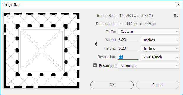
Scaling the image in Photoshop.
3. Save the image in the JPEG format and quit Photoshop.
4. Start a new project in Revit (or open an existing Revit project). Use the Architectural template.

Starting a New Project in Revit.
5. On the Ribbon: Insert > Import > Image.

Inserting the image in Revit.
6. Navigate to the file location and click Open.
7. In the Revit Drawing Area, click to place the image.
8. With the image selected, type ZE. (This command zooms the view to show the whole project.)
9. In this example, we already know that the image is at a resolution of 72 pixels per inch and that it represents a drawing at a scale of 1/8” = 1’-0”. Therefore, no further scaling is required. (But click here for further discussion of the scaling question.)
10. You may need to reposition the image in the center of the Revit workspace. If so, click and drag the image, or use the Move tool (type MV, or find it on the Ribbon at Modify > Modify > Move).
11. If necessary, adjust the location of the elevation tags in the Drawing Area by selecting and dragging them to the correct location (e. g., adjacent to the four sides of the floor plan).

Elevation tags prior to repositioning (left) and elevation tags after repositioning (right).
12. You can now proceed to trace the plan, for example by using the Wall tool on Revit’s Architecture > Build panel. (Refer to the tutorial on Basic Building Shell + Floors.)


