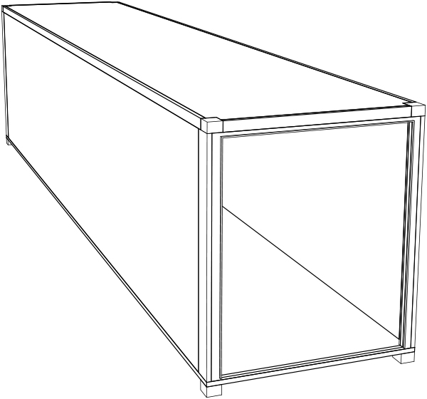
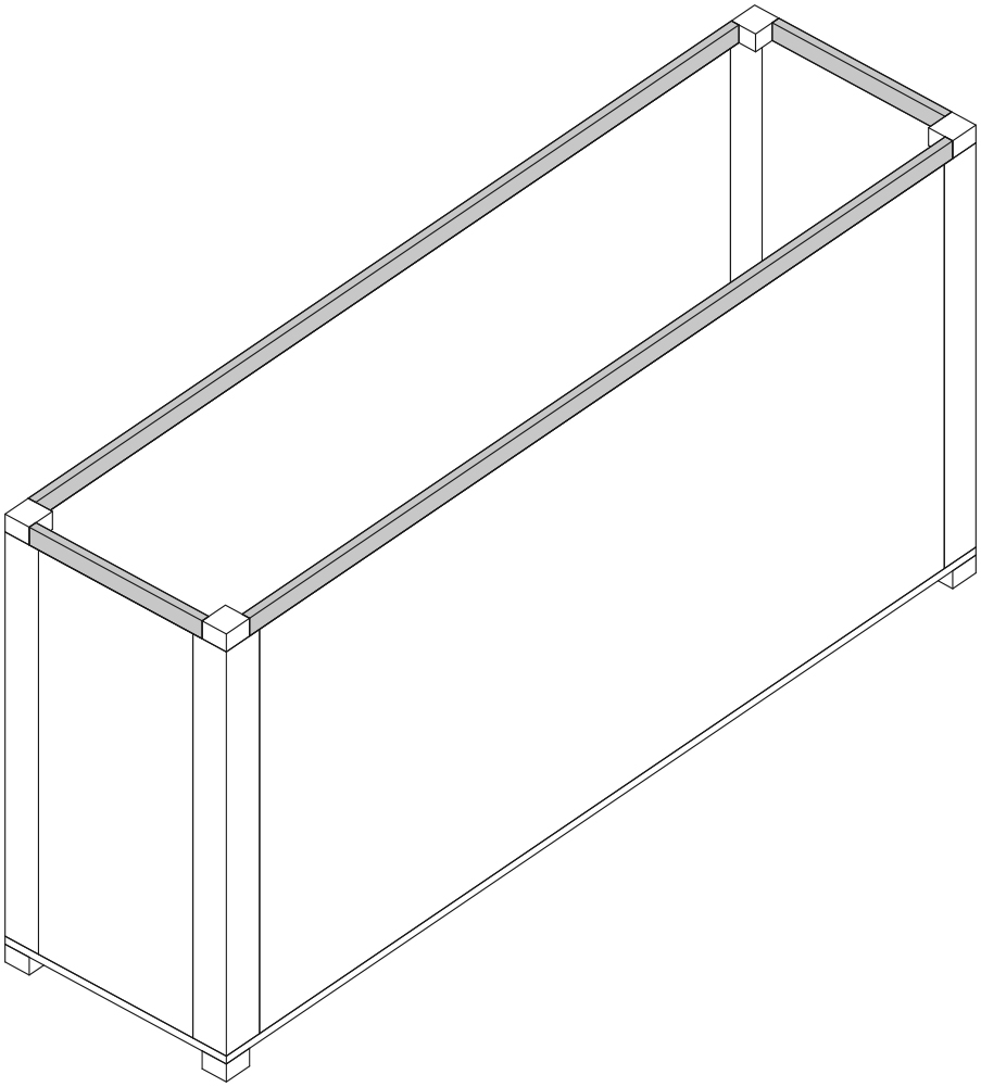
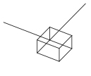
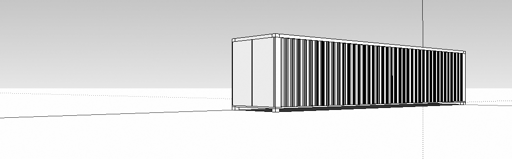
This step-by-step tutorial is a brief introduction to basic modeling tools in SketchUp. It leads to the creation of a simplified model of a shipping container (shown below).
1 SET UP YOUR PROJECT:
1.1 Start SketchUp and begin a New File.
File > New.
1.2 Set up the drawing layers.
Choose Window > Layers. This opens the Layers palette. Using this palette, click the New Layer button to create layers named GRID, WALLS, FLOOR, ROOF, and DOOR. Set each layer to a unique color. These layers will store the objects you build. Layer names and colors are arbitrary. In particular, colors should not be expected to bear any relationship to the material being represented. It is conventional to choose distinct colors to make it easy to visually discern objects in different layers.
1.3 Enable the Getting Started and Views toolbars.
Choose View > Toolbars and check the boxes next the Getting Started and Views. All other toolbars can be unchecked. These toolbars contain the basic set of tools.
1.4 Set the GRID layer as the current layer.
In the Layers palette, click the radio button next to the GRID layer. The current layer will receive any newly created objects.
1.5 Erase the human figure.
Click on the human figure and press [Delete]. The human figure is provided for scale.
1.6 Draw a base rectangle.
Click on the Rectangle tool (or press [R]). Click the origin (the point where all three axes intersect) to begin the rectangle. Next, type 38’4,7’5 (these dimensions will appear in the Dimensions box at the lower right-hand corner of the screen as you type them). This base rectangle does not represent a built component. Instead, it measures the distance between alignment holes in the shipping container.
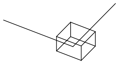
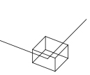
1.7 Zoom out.
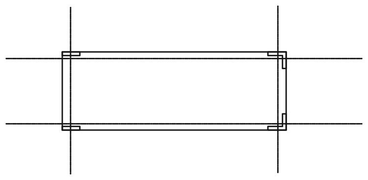
Choose Camera > Zoom Extents. The model should appear like the diagram below.

2 CONSTRUCT CORNER BLOCKS:
2.1 Set FLOOR as the current layer.
In the Layers palette, click the radio button next to the FLOOR layer. The current layer will receive any newly created objects.
2.2 Zoom in on the lower right-hand corner of the base rectangle.
Spin the center wheel on the mouse. Zooming in gives you the ability to work with greater precision.
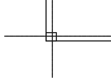
2.3 Begin a rectangle at the intersection of the gridlines.
Press [R]. Hover the mouse over the corner of the rectangle until the Endpoint indicator appears. Click the mouse button.
2.4 Complete the rectangle.
Move the mouse down and to the right. Type 7,6.5. Typing dimensions in this way tells SketchUp the size of the rectangle. Because you are indicating orientation with the direction of the mouse, you don’t need to enter negative coordinates.
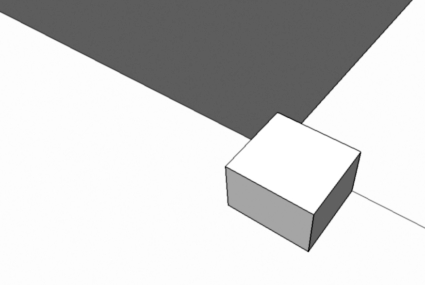
2.5 Use the Push/Pull tool to construct a box.
Click the Push/Pull tool. Click on the rectangle you just drew. Type 4.5 for the Distance (height). At this point, the model should look like the diagram below (zoomed-in view). The Push/Pull tool will extrude any closed shape.
2.6 Convert the box into a Group.
Select the box you just drew by drawing a window around it. Choose Edit > Make Group. Grouping the box will allow it to move independently of other objects.
2.7 Rotate the view to see the box from the interior side of the shipping container.
(See diagram below.) Hold and drag the mouse wheel to rotate the view.
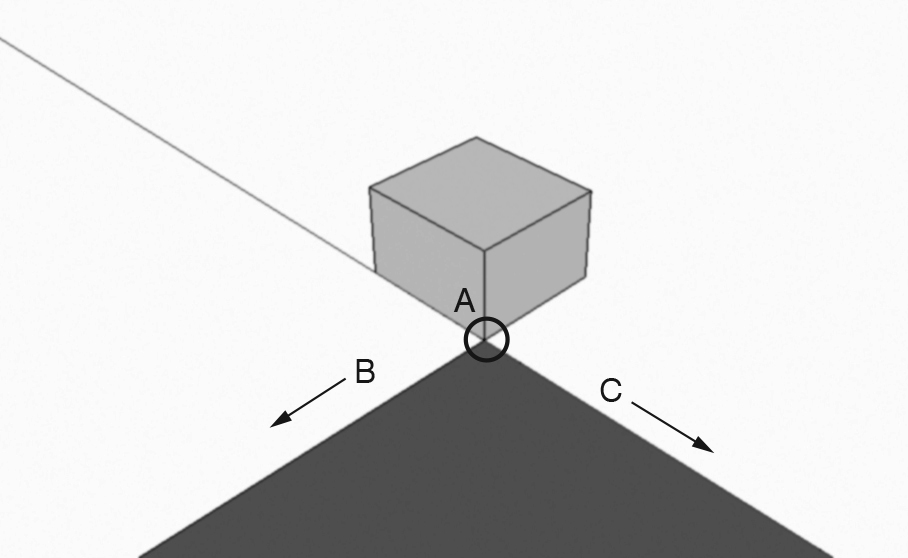
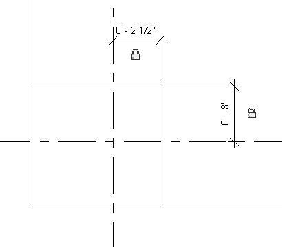
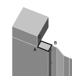
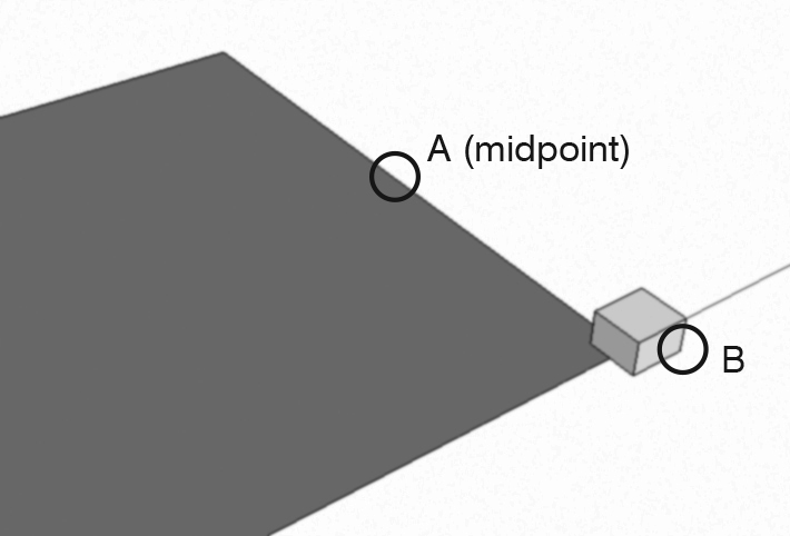
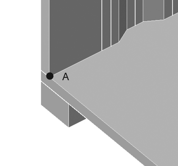
2.8 Begin to move the box into the correct position.
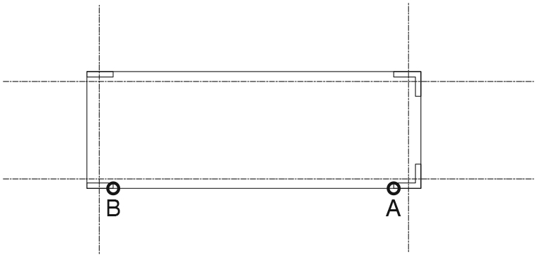
Select the box. Click the move tool. Click on the point marked A to begin the move operation. Move the mouse in the direction marked with B-arrow. Type 3. In precision model-building, it is sometimes easier to construct SketchUp objects in a temporary, incorrect position, and then to move the objects into their permanent, correct position.
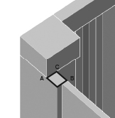
2.9 Complete the move.
Select the box. Click the move tool. Click on the point marked A to begin the move operation. Move the mouse in the direction marked with C-arrow. Type 2.5. The model should look like the diagram below (zoomed-in view).

2.10 Zoom out.
Choose Camera > Zoom Extents. This causes SketchUp to display the entire model.
2.11 Rotate the view to the position shown below.
Hold and drag the mouse wheel to rotate the view.
2.12 Construct a temporary rectangle.
Press [R]. For the first point, click point A in the diagram above. For the second point, click point B. This rectangle will be used to “mirror” or “flip” a copy of the corner box to the opposite side of the container base. Because SketchUp does not have a native “mirror” tool, we will use the Scale tool with a value of -1 (negative 1).
2.13 Copy-Paste the corner box in place.
Select the box and choose Edit > Copy. Then choose Edit > Paste in Place. This “pasted-in-place” box will be “flipped” to the opposite side of the container base.
2.14 Group the copied box and the temporary rectangle.
Double-click on the temporary rectangle; hold down [Shift] and click on the box. Choose Edit > Make Group. Grouping permits the objects to be flipped without affecting adjacent objects.
2.15 Invoke the Scale tool.
Choose Tools > Scale or click on the Scale tool. Click on the “grip” at the center of the box face (point A in the diagram below). Begin moving the mouse in direction B as shown. Type -1 (negative 1). Click on the Select tool (the arrow tool) to complete the command. This command “flips” the objects to the opposite side of the container base.

2.16 Explode the temporary group and erase the temporary rectangle.
Select the “flipped” box and rectangle. Choose Edit > Group > Explode. Exploding a group returns it to its constituent objects.
2.17 Mirror the two corner boxes to the opposite side of the rectangle.
Repeat the previous set of commands (steps 2.12-2.16), but select both corner boxes this time, and mirror them around the other axis (see diagram below).

3 CONSTRUCT THE FLOOR:
3.1 Build the floor.
Use the Rectangle and Push/Pull tools to construct a box representing the floor. The base of the box should coincide with the outside, top corners of the corner boxes; its height is 2”.
3.2 Group the floor and the four corner boxes.
Draw a window around the floor and the four corner boxes. Choose Edit > Make Group.
4 CONSTRUCT CORNER POSTS:
4.1 Set WALLS as the current layer.
In the Layers palette, click the radio button next to the WALLS layer. The current layer will receive any newly created objects.
4.2 Zoom in on the lower right-hand corner of the base.
Spin the center wheel on the mouse.
4.3 Draw a rectangle for the front corner post.
Press [R]. Click on the lower right-hand corner of the floor. Move the mouse into the floor and type 9.5,2.
4.4 Use the Push/Pull tool to construct a box.
Click the Push/Pull tool. Click on the rectangle you just drew. Type 7’7 for the Distance (height).
4.4 Zoom out.
Choose Camera > Zoom Extents.
4.5 Zoom in on the lower left-hand corner of the base.
Spin the center wheel on the mouse.
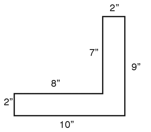
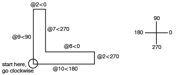
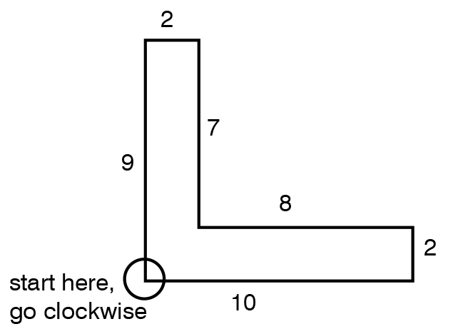
4.6 Draw the outline of the rear corner post.
Click the Pencil tool. Click on the lower left-hand corner of the floor to begin drawing an outline of the corner post. Refer to the diagram below for dimensions. Starting at the lower left-hand corner, continue clockwise around the outline. For each new point, check that the direction is parallel with a major axis (the drawing lines will highlight red, green, or blue as appropriate). Type the numbers as written. The Pencil tool creates straight line segments. A closed set of segments can be used as the base for the Push/Pull tool, as shown in the next step.
4.7 Use the Push/Pull tool to extrude the outline vertically, creating the corner post.
Click the Push/Pull tool. Click on the outline you just drew. Type 7’7 for the Distance (height).
5 CONSTRUCT THE SIDE WALL:
5.1 Set a top view and zoom in on an empty space outside the model.
Click on the Top tool. Choose Camera > Zoom Window and zoom in on a small empty area.
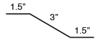
5.2 Draw the centerline of a wall panel.
Click on the Pencil tool. Draw a line 1.5” long. From its right endpoint, draw a second line 3”. Use the Rotate tool to rotate the second line 30 degrees clockwise. From the right endpoint of the rotated line, draw a third line 1.5” long. Refer to the diagram below for dimensions. Again, in this step, we are creating objects in a temporary, incorrect position, so that we can move them into their permanent, correct position later.

5.3 Offset the centerline to create the edges of the wall panel.
Select the three lines just drawn. Then choose Tools > Offset. Click on the left endpoint of the connected lines. Begin to move the mouse up (vertically). Type 1/16 to set the offset distance. Repeat this step, except move the mouse down, creating another offset below the three connected lines. The OFFSET command creates a copy of the original objects, “offset” by a specified distance.
5.4 Erase the original three lines.
Click on the original three lines to select them and press [Delete].
5.5 Join the edges of the wall panel.
Use the Pencil tool to draw a line at each end of the panel outline to “cap” it. Refer to the diagram below. Capping the figure creates a planar shape which can be Push/Pulled.

5.6 Set a perspective view.
Click on the Iso tool.
5.7 Zoom out.
Choose Camera > Zoom Extents.
5.8 Zoom in on the outline you just drew.
Spin the mouse wheel or choose Camera > Zoom Window.
5.9 Use the Push/Pull tool to extrude the outline vertically, creating the corner post.
Click the Push/Pull tool. Click on the outline you just drew. Type 7’7 for the Distance (height).
5.10 Group the wall panel.
Triple-click on the wall panel to select it. Choose Edit > Make Group.
5.11 Move the wall panel into position.
Click on the wall panel to select it. Click the Move tool. For the base point, click the back corner of the panel. For the second point, click the corner of the corner post. Refer to the diagram below to see the correct position.

5.12 Copy-paste the panel in place.
Click the panel to select it. Choose Edit > Copy and Edit > Paste in Place.
5.13 Flip the panel along its Green axis.
Click the panel to select it. Right-click and choose Flip Along > Group’s Green.
5.14 Move the flipped panel into its correct position.
Refer to the diagram below.

5.15 Zoom in on the base of the two panels.
Spin the mouse wheel or choose Camera > Zoom Window.
5.16 Array the panel.
Select the two wall panels and click the Move tool. Click [Ctrl] to invoke the tool’s Copy mode. (A small plus sign will appear next to the pointer.) Click on point A in the diagram above, and then click on point B. Type *39 (asterisk 39) and press [Enter]. This procedure is used to make 39 copies of the two objects. It is known as creating an “array.”
5.17 Zoom out.
Choose Camera > Zoom Extents.
5.18 Zoom in on the lower right-hand corner of the container.
Spin the mouse wheel or choose Camera > Zoom Window.
5.19 Fill the gap in the wall.
Use the Rectangle and Push/Pull tools to build a box filling the gap between the final wall panel and the corner post.
6 CONSTRUCT OBJECTS AT TOP OF WALL:
6.1 Zoom out.
Choose Camera > Zoom Extents.
6.2 Explode the group of objects at the base of the model.
Click on the floor and choose Edit > Group > Explode.
6.3 Copy the corner blocks to the top of the wall.
Select the corner blocks (from the FLOOR layer). Click the Move tool and press [Ctrl] to invoke the Copy mode. Copy them vertically so that they are set on top of the corner posts.
6.4 Change the layer of the copied corner blocks.
With the copied corner blocks still highlighted, choose Window > Entity Info. Assign these objects to the WALLS layer. The Entity Info window allows you to change the layer of selected objects.
6.5 Zoom in on the top of the left end of the wall.
Spin the center wheel on the mouse, or type Z at the Command prompt and drag the mouse to define a zoom window.
6.6 Draw a rectangle on the top corner block.
Press [R]. Draw a rectangle as shown in the diagram below (click on points A and B).
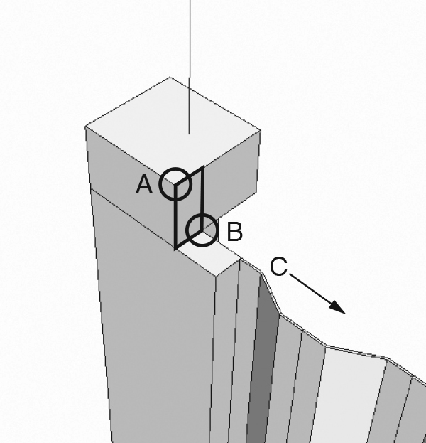
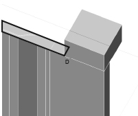
6.7 Begin to build a rail along the top of the wall.
Use the Push/Pull tool to extrude the rectangle in the direction marked C in the diagram above. (If you see an error message about “Offset Limited to 3”,” accept the extrusion and then repeat the Push/Pull tool in the direction marked C.)
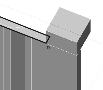
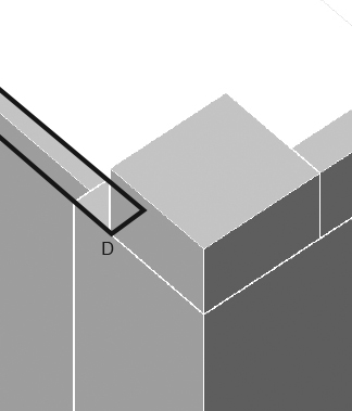
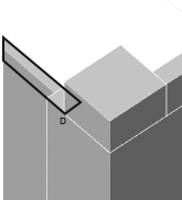
6.8 Continue the rail across the entire wall.
Push/Pull the face to point D in the diagram below.

7 MIRROR OBJECTS:
7.1 Zoom out.
Choose Camera > Zoom Extents.
7.2 Draw a temporary reference line.
Click the Pencil tool. Draw a line from the midpoint of one of the short sides of the floor, parallel with the red axis, away from the shipping container. (We will erase this line later.)
7.3 Isolate the WALLS layer. In the Layers palette, turn off all layers except the WALLS layer.
Isolating a layer sometimes makes it easier to work.
7.4 Group the objects in the WALLS layer, except for the temporary reference line.
Draw a window around the objects and choose Edit > Make Group.
7.5 Mirror the objects in the WALLS layer.
Use a procedure like that described in steps 2.12-2.16, above, to mirror the objects in the WALLS layer around the temporary reference line.
7.6 Erase the temporary reference line.
Click on the temporary reference line and press [Delete].
8 CONSTRUCT THE REAR WALL:
8.1 Restore the previous layer settings.
In the Layers palette, turn on all layers.
8.2 Rotate the view so you are looking at the back of the container.
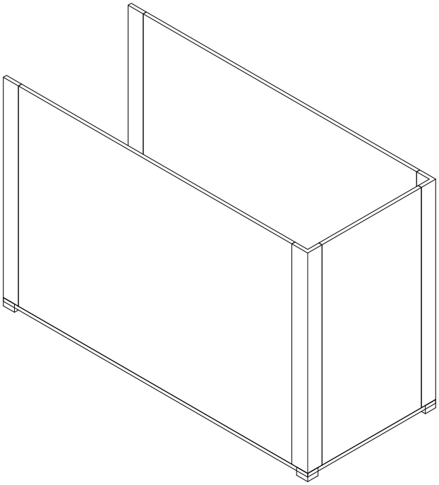
(Refer to the picture below.) Press and drag the mouse wheel to rotate the view.

8.3 Build a rear wall, using the Rectangle and Push/Pull tools.
Press [R]. For the first corner, click on a point away from the shipping container (we will move the box into its correct position later). For the other corner of the box base, type 1,6’6. For the height, type 7’7.
8.4 Group the wall.
Select the wall you just drew (triple-click the wall) and choose Edit > Make Group.
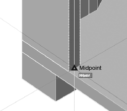
8.5 Move the wall into its correct position.
Select the rear wall. Use the Move tool to set it in place, so that its outer face aligns with the midpoint of the corner post as shown in the figure below.

8.6 Zoom in on the top of the rear wall.
Spin the mouse wheel or choose Camera > Zoom Window. (See the diagram below.)

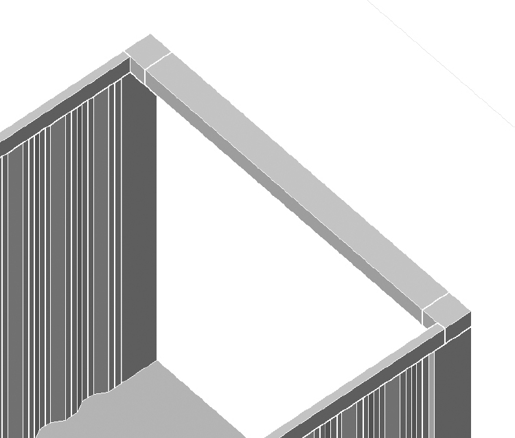
8.7 Construct a rectangle along the top of the rear wall.
Press [R]. For the first point, click point A in the diagram above. Zoom out by spinning the mouse wheel, and complete the rectangle by clicking on point B in the diagram below.

8.8 Extrude the rectangle to its correct height.
Click the Push/Pull tool. Click on the rectangle you just drew, and extrude its height to 4.5”.
8.9 Group the box you just drew.
Triple-click to select the box and choose Edit > Make Group.
9 CONSTRUCT THE ROOF:
9.1 Zoom out.
Choose Camera > Zoom Extents.
9.2 Zoom in on the right side (the front) of the shipping container.
Spin the center wheel on the mouse, or type Z at the Command prompt and drag the mouse to define a zoom window.
9.3 Build a box across the top of the door opening using the Rectangle and Push/Pull tools.
Use the points on the corner boxes to set the dimensions of the box base. If you use the points at the top of the corner boxes, you can set the height as -4.5 (negative 4.5) and the box will fit between the corner boxes as shown in the diagram below.
9.4 Set ROOF as the current layer.
In the Layers palette, click the radio button next to the ROOF layer. The current layer will receive any newly created objects.
9.5 Zoom out.
Choose Camera > Zoom Extents.
9.6 Draw two rectangles to fill the roof.
Use the Rectangle tool to construct two rectangles (1) and (2) as shown in the diagram below.

9.7 Isolate the ROOF layer.
In the Layers palette, turn off all layers except the ROOF layer.
9.8 Extrude the roof.
Use the Push/Pull tool to extrude the two rectangles you just drew. Extrude them downwards to a depth of 1”.
10 CONSTRUCT THE DOOR:
10.1 Restore the previous layer settings.
In the Layers palette, turn on all layers.
10.2 Set DOOR as the current layer.
In the Layers palette, click the radio button next to the DOOR layer. The current layer will receive any newly created objects.
10.3 Rotate the view so you are looking at the front of the container.
(Refer to the picture below.) Press and drag the right mouse button to rotate the view.

10.4 Build the first door using the Rectangle and Push/Pull tools.
Press [R]. For the first corner, click on a point away from the shipping container (we will move the box into its correct position later). For the other corner of the box base, type @1,3’9.5”. For the height, type 7’7.
10.5 Group the door.
Triple-click to select the door you just drew, and choose Edit > Make Group.
10.6 Copy the door.
Use the Move tool with the Copy option (press [Ctrl] to invoke the Copy option).
10.7 Move the first door into its correct position.
Select the first door and use the Move tool to set it in place, so that its inner face aligns with the point marked A in the figure below.
10.8 Repeat the previous step with the second door. The model is complete.