This tutorial begins with a line drawing extracted from a 3D model of a masonry building. The tutorial shows how the line drawing can be developed in AutoCAD and Illustrator into a presentation-quality drawing.
Step 1. Open a line drawing of a wall section. (In this tutorial, the original line drawing was extracted from a Rhino model. To see this process, refer to the tutorial titled Rhino to AutoCAD Workflow: Cutting a Section.)
Initially, the line drawing is undifferentiated with respect to lineweight, material notations, dimensions, and hatch patterns:

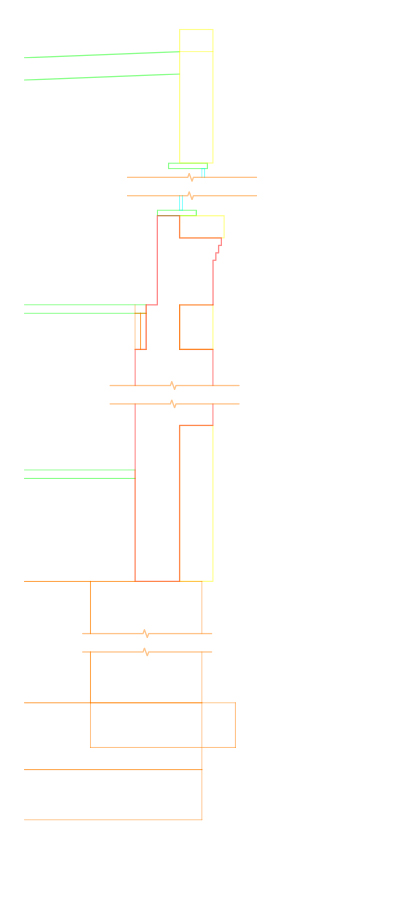
Step 2. In AutoCAD, define several new layers corresponding to a categorization scheme. For example, different layers could correspond to different materials, or different layers could correspond to different lineweights.
Once you have defined the new layers, assign each of the objects (lines) in the drawing to one of the layers. The image below shows one possible categorization scheme, where the layers represent different materials (e. g., brick and stone):
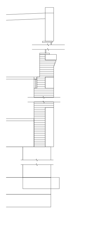
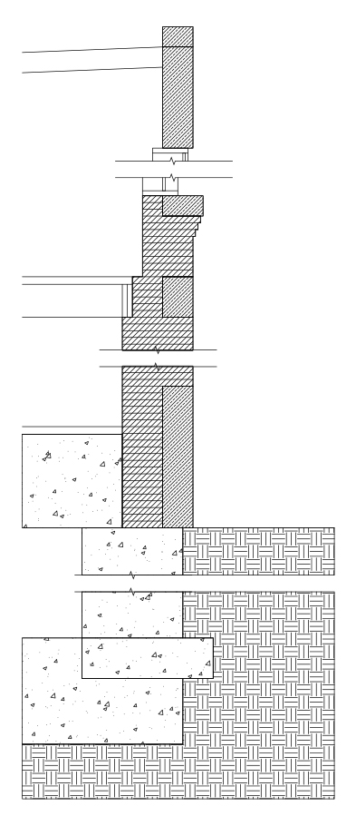
Step 3. Add detail lines to the drawing. The image below shows one step in this process, where detail lines are added to represent horizontal joints between successive brick courses.
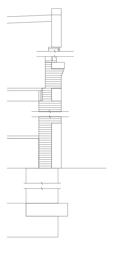
Step 4. Continue the process of adding detail lines. In the image below, detail lines are drawn to show “elements beyond” the cutting plane – specifically, lines representing the window jambs and lines representing the bottom edges of floor joists.
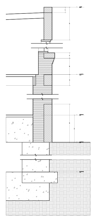
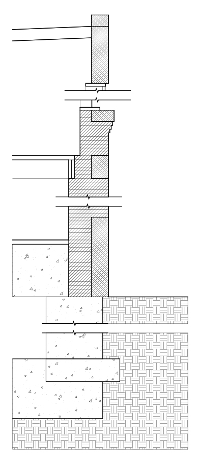
Step 5. Add hatch patterns to materials as appropriate:
Step 6. Save the AutoCAD drawing in 2007 .dwg format and open it in Illustrator. (This will preserve the layer assignments.) In Illustrator, assign lineweights as appropriate for scale:
Step 7. Add notes and dimensions as appropriate for scale. (Alternatively, notes and dimensions can be added in AutoCAD and imported to Illustrator with the other information.)