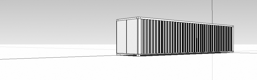
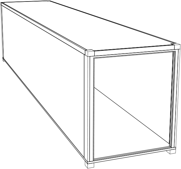
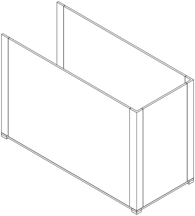
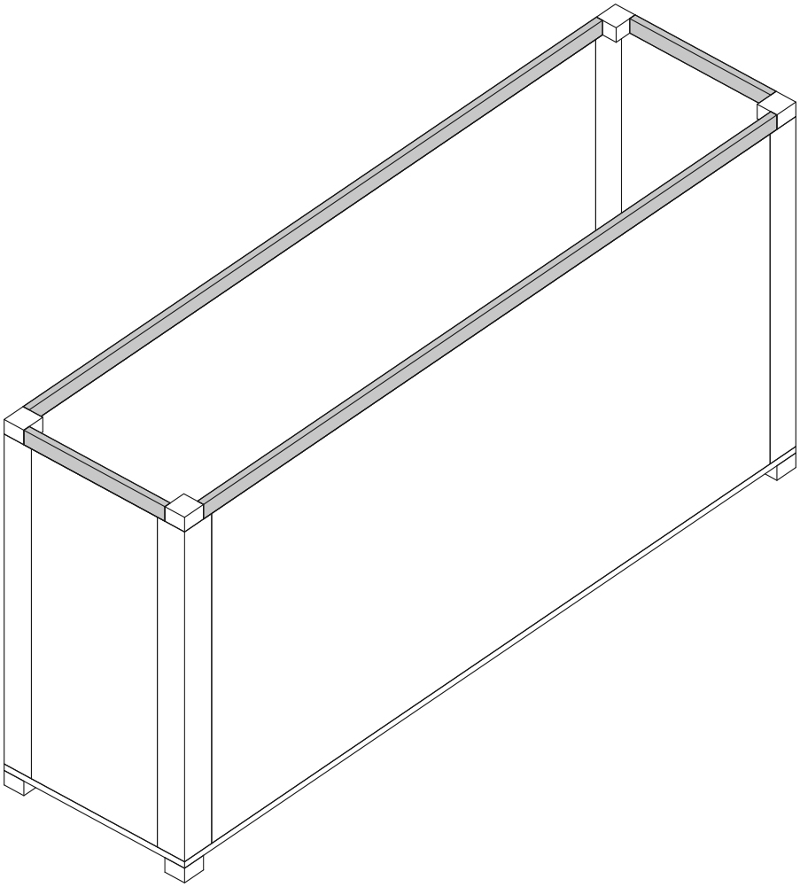
This step-by-step tutorial is a brief introduction to basic modeling tools in Revit. It leads to the creation of a simplified model of a shipping container (shown below).

1 SET UP YOUR PROJECT:
1.1 Open Revit and begin a New Project.
Under the [Application Menu] (upper left hand corner of the screen), choose New Project; use the Architectural template. See [F1] > Revit Users > Start a Project > Creating a Project from the Application Menu.
1.2 Set the East Elevation as current.
In the Project Browser (left side of screen), double-click on the East elevation view. The Project Browser is a palette, the visibility of which is controlled by View > Windows > User Interface. By default it is docked to the left side of the screen. In Revit, one view is always current (i. e. you are always viewing your model from a certain point, direction, and projection). The behavior of certain commands is affected by the view. (For example, new Levels can only be added while viewing the project in elevation.) See [F1] > Revit Users > Introduction to Revit > User Interface > Project Browser.
1.3 Set up Levels named Floor and Roof.
Zoom in on the Level labels on the right side of the view (spin the mouse wheel, or type ZR to zoom in on a region). Double-click on the text reading “Level 2” to change it to “Roof.” When prompted to rename corresponding views, choose Yes. Repeat this procedure and change “Level 1” to “Base.” Levels are fundamental ordering devices within Revit. They can be added, deleted, renamed, and modified within Elevation views. Use Levels as references to locate floors, tops of walls, bottoms of foundations, window sills, etc. Renaming a level is usually done to make the name correspond with some desired building element (e. g., top of roof, bottom of footing, etc.). Renaming the corresponding views simply ensures that the reference will appear consistently throughout the model. See [F1] > Revit Users > Preliminary Design > Levels and Grids > Levels > Adding Levels.
1.4 Create a new Level named Ground.
Click the Modify tool. Next, on the Architecture tab, Datum panel, choose the Level tool. Zoom out to the full extents of the view (type ZE). Hover the mouse at the far left end of the Base Level line. Move the mouse slightly below the line endpoint and click to begin drawing a new Level. (The exact position of the new Level doesn’t matter at this point). Click the mouse again beneath the right endpoint of the Base Level line. Double-click on the text reading “Level 3” to change it to “Ground.” Double-click on the text indicating the height position of the Ground Level and change it to -6.5” (negative six-and-a-half inches). Click on the Modify tool to complete the task. Creating a new level doesn’t add any building elements, only a reference line and associated views (e. g., Floor Plan and Ceiling Plan). Clicking Modify on the Architecture tab is the equivalent of telling Revit that you have completed a task and are about to begin a new one. The same effect is achieved by clicking the [esc] key repeatedly (until the Modify tool highlights).
1.5 Make the Base Floor Plan current.
In the Project Browser, under Floor Plans, double-click on Base. See [F1] > Revit Users > Document and Present the Project > 2D Views > Plan Views.
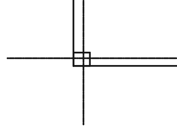
1.6 Set up two sets of parallel gridlines, establishing a horizontally oriented rectangle.
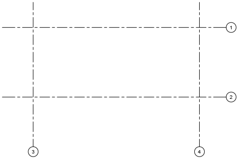
On the Architecture tab, Datum panel, choose the Grid tool. Use this tool to draw gridlines as shown in the diagram below. (The exact position of the gridlines and the numbers in the grid bubbles do not matter at this point.) Click the Modify tool to complete the task. See [F1] > Revit Users > Preliminary Design > Levels and Grids > Grids > Adding Grids.
2 Construct a floor and change the floor type:
2.1 Begin to construct a floor on the Base Level.
On the Architecture tab, Build panel, choose the Floor tool. Next, on the Modify|Create Floor Boundary tab, Draw panel, click the Rectangle tool. Use this to draw a rectangle aligning with the intersections of the gridlines you drew in the previous step. See [F1] > Revit Users > Build the Model > Architectural Modeling > Floors.
2.2 Offset the long edges of the rectangle.
On the Modify|Create Floor Boundary tab, Modify panel, choose the Offset tool. In the Options bar, set the Numerical Offset to 3.5” (three-and-a-half inches). Check the “Copy” box OFF. Next, click on the two long edges of the rectangle to offset them to the outside of the gridlines. (Note that Revit will prompt you graphically to offset to either side of the existing line; click to accept Revit’s prompt.) The Offset tool makes a parallel copy of an existing object. See [F1] > Revit Users > Tools and Techniques > Editing Elements > Moving Elements > Moving Elements with the Offset Tool.
2.3 Offset the short edges of the rectangle.
Repeat the previous step, but with a Numerical Offset of 4.5” on the short edges. Click the Modify tool to complete the task.
2.4 Lock the floor-to-gridline relationships.
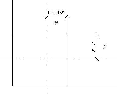
On the Annotate tab, Dimension panel, choose the Aligned tool. Use this tool to create a dimension between one of the gridlines and the adjacent rectangle edge. (The dimension should equal the offset you just drew.) When you see a padlock symbol, click it to “lock” the padlock. Repeat this step on all four sides of the rectangle. Locking elements to gridlines means that if the gridline is moved, the elements will move with the gridline. This is a very important concept in Revit. See [F1] > Revit Users > Document and Present the Project > Annotating > Dimensions > Permanent Dimensions > Placing Permanent Dimensions > Aligned Dimensions.
2.5 Complete the floor.
On the Modify|Create Floor Boundary tab, Mode panel, click the green check mark to complete the floor.
2.6 Test the flexibility of the gridlines.
Use the Modify tool to select and move the gridlines. The floor edge should move together with each of the gridlines. If it does not, or if you see an error message about constraints, redo the previous steps.
2.7 Change the floor type.
Use the Modify tool to select the floor (click on the floor edge to select it). In the Properties palette, click the Edit Type button. In the resulting Type Properties dialog box, click Duplicate. Give the duplicate type the name Container – 2” and click OK. Still within the Type Properties dialog box, next to the Structure parameter, click Edit. Change the Thickness to 2” (2 inches) and click OK. Click OK again to exit the Type Properties dialog box. See [F1] > Revit Users > Build the Model > Architectural Modeling > Floors > Changing the Floor Type.
3 CREATE AND PLACE CORNER BLOCKS:
3.1 Make the Ground floor plan current.
In the Project Browser, under Floor Plans, double-click on Ground.
3.2 Begin a New Family definition.
Under the [Application Menu] (upper left hand corner of the screen), choose New Family. Choose the Generic Model two level based template file. Click Open. In Revit, Families are used to organize comment components and symbols. Revit has several system families and you can also define custom families. See [F1] > Revit Users > Build the Model > Revit Families and also [F1] > Revit Users > Customize Revit > Creating Loadable Families.
3.3 Create an extrusion.
On the Create tab, Forms panel, choose the Extrusion tool. Next, on the Modify | Create Extrusion tab, Draw panel, choose the Rectangle tool. Use this tool to draw a rectangle measuring 6.5” x 7”, with one of its corners at the intersection of the reference lines. On the Modify | Create Extrusion tab, Mode panel, click the green check mark to complete the extrusion. See [F1] > Revit Users > Customize Revit > Creating Loadable Families > Creating Family Geometry > Constraining Family Geometry.
3.4 Lock the extrusion to the reference levels.
In the Project Browser, double-click on the Back Elevation view. In the Back Elevation view, select the extrusion (it is represented as a rectangle on the Lower Ref. Level). Drag the triangular handle at the top of the extrusion vertically until it reaches the Upper Ref. Level. Click on the padlock symbol to “lock” the padlock. Repeat this procedure for the handle on the Lower Ref. Level (you will need to drag the handle away from the level and back again). Click the Modify tool to complete the procedure. The Reference Levels refer to actual Levels in your project. Because the family component can be placed on any level, the Family Editor uses the term “Reference Level.”
3.5 Save the family.
Under the [Application Menu], choose Save. Save the family as corner_block.rfa.
3.6 Load the family into your project.
On the Modify tab, Family Editor panel, choose Load into Project (the .rvt file). See [F1] > Revit Users > Build the Model > Revit Families > Loading and Saving Families.
3.7 Check that the corner_block component is ready to place.
In the Properties palette, check that “corner_block” is visible. If it is not, choose the Place a Component tool (Architecture tab, Build Panel, Component > Place a Component). See [F1] > Revit Users > Build the Model > Architectural Modeling > Components > Placing Components.
3.8 Place the corner_block component.
Zoom into the lower left-hand corner of the Ground Floor Plan. Click to place the family at the corner of the floor as shown in the diagram below.

3.9 Change the Visual Style to Wireframe.
On the View Control Bar, click the cube icon and select Wireframe.
3.10 Check the family’s reference levels.
Make sure the component is selected. In the Properties palette, set the component’s Base Level to Ground and the Top Level to Base. Set the Top Offset to -2” (negative two inches).
3.11 Mirror the corner block around the short side of the floor.
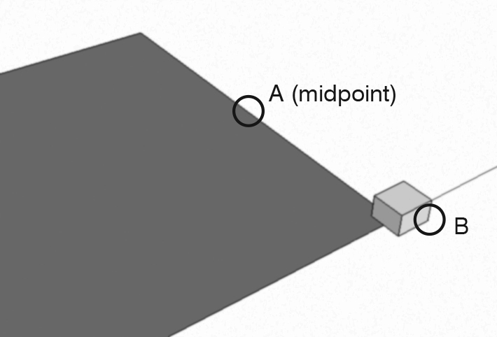
Use the Modify tool to select the corner_block family. On the Modify | Generic Models tab, Modify panel, choose the Mirror – Draw Axis tool. To draw a mirror axis, hover the mouse over the midpoint of the short side of the floor rectangle until the Midpoint snap indicator appears. Click on this point. Next, click on a second point exactly to the right or left of this point to establish a horizontal mirror line. The corner_block family is mirrored to the opposite corner.
3.12 Mirror two corner blocks around the long side of the floor.
Repeat the previous step, but select both corner_blocks, and mirror them around the midpoint of the long side of the floor rectangle. Refer to the diagram below.

3.13 Change the View Scale to 3” = 1’-0”.
On the View Control bar, click the text reading 1/8” = 1’-0” and change it to 3” = 1’-0”. The View Scale setting controls the display of elements and objects in a drawing (e. g., annotation, dimensions, material patterns). In this example it will make the annotations easier to read, relative to the size of the building being modeled. See [F1] > Revit Users > Document and Present the Project > Use and Manage Views > Changing the Graphics of a View > View Scale.
3.14 Zoom into the lower left-hand corner of the floor.
Spin the mouse wheel or type ZR.
3.15 Lock the block-to-gridline relationships and the overall block dimensions for each of the copied corner_blocks.
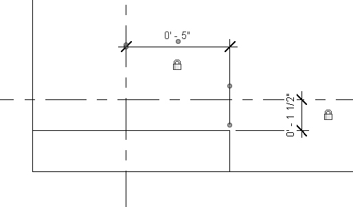
On the Annotate tab, Dimension panel, choose the Aligned tool, and use it to dimension the component-to-gridline relationships, making sure to click the padlock symbol to “lock” the padlock. Refer to the diagram below. Repeat this procedure for the instance of the corner_block component at the other corner of the floor.

3.16 Zoom out.
Spin the mouse wheel or type ZE.
3.17 Test the flexibility of the gridlines.
Use the Modify tool to select and move the gridlines. The corner blocks should move together with each of the gridlines. If they do not, or if you see an error message about constraints, redo the previous steps.
4 CREATE AND PLACE FRONT CORNER POSTS:
4.1 Make the Base floor plan current.
In the Project Browser, under Floor Plans, double-click on Base.
4.2 Begin a New Family definition.
Under the [Application Menu] (upper left hand corner of the screen), choose New Family. Choose the Generic Model two level based template file. Click Open. This takes you into the Family Editor.
4.3 Create an extrusion.
On the Create tab, Forms panel, choose the Extrusion tool. Next, on the Modify | Create Extrusion tab, Draw panel, choose the Rectangle tool. Use this tool to draw a rectangle measuring 2” x 9.5”, with one of its corners at the intersection of the reference lines. On the Modify | Create Extrusion tab, Mode panel, click the green check mark to complete the extrusion.
4.4 Lock the extrusion to the reference levels.
Using the same procedure you used for the corner_block family, lock the top and bottom of the extrusion to the Upper and Lower Reference Levels.
4.5 Save the family.
Under the [Application Menu], choose Save. Save the family as corner_post_front.rfa.
4.6 Load the family into your project.
On the Modify tab, Family Editor panel, choose Load into Project (the .rvt file). Zoom in to the Base Floor Plan to place the family at the corner of the floor. Once placed, mirror it to the opposite corner. Refer to the diagram below.

4.7 Change the View Scale to 3” = 1’-0”.
On the View Control bar, click the text reading 1/8” = 1’-0” and change it to 3” = 1’-0”.
4.8 Lock the family to the gridlines.
On the Annotate tab, Dimension panel, choose the Aligned tool, and use it to dimension the component-to-gridline relationships, making sure to click the padlock symbol to “lock” the padlock. Refer to the diagram below. Repeat this procedure for the instance of the component at the other corner of the floor.
4.9 Test the flexibility of the gridlines.
Use the Modify tool to select and move the gridlines. The corner blocks should move together with each of the gridlines. If they do not, or if you see an error message about constraints, redo the previous steps.
5 CREATE AND PLACE REAR CORNER POSTS:
5.1 Begin a New Family definition.
Under the [Application Menu], choose New Family. Choose the Generic Model two level based template file. Click Open.
5.2 Create an extrusion.
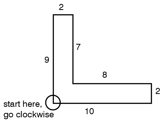
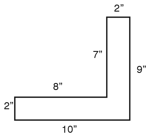
On the Create tab, Forms panel, choose the Extrusion tool. Next, on the Modify | Create Extrusion tab, Draw panel, choose the Line tool. On the Options bar, check “Chain” on. Use the Line tool to draw a figure corresponding with the diagram below, with the outside corner of the “L” at the intersection of the reference lines. On the Modify | Create Extrusion tab, Mode panel, click the green check mark to complete the extrusion.
5.3 Lock the extrusion to the reference levels.
Using the same procedure you used for the corner_post_front family, lock the top and bottom of the extrusion to the Upper and Lower Reference Levels.
5.4 Save the family.
Under the [Application Menu], choose Save. Save the family as corner_post_rear.rfa.
5.5 Load the family into your project.
On the Modify tab, Family Editor panel, choose Load into Project (the .rvt file). Zoom in to the Base Floor Plan to place the family at the corner of the floor. Once placed, mirror it to the opposite corner. Refer to the diagram below.

5.6 Lock the family to the gridlines.
On the Annotate tab, Dimension panel, choose the Aligned tool, and use it to dimension the component-to-gridline relationships, making sure to click the padlock symbol to “lock” the padlock. Refer to the diagram below. Repeat this procedure for the instance of the family at the other corner of the floor.

5.7 Zoom to the extents of the model.
Type ZE.
5.8 Check the corner_post component for position and flexibility.
Use the Modify tool to select and move the gridlines. The floor edge and the family instances (the corner posts) should move together with each of the gridlines. If they do not, or if you see an error message about constraints, redo the previous steps.
6 CREATE WALLS:
6.1 Begin the construction of a side wall.
On the Architecture tab, Build Panel, choose the Wall: Architectural tool. See [F1] > Revit Users > Build the Model > Architectural Modeling > Walls.
6.2 Edit the wall type.
In the Properties palette, make sure the Basic Wall – Generic 8” type is current. click the Edit Type button. In the resulting Type Properties dialog box, click Duplicate. Give the duplicate type the name Container – Corrugated and click OK. Still within the Type Properties dialog box, next to the Structure parameter, click Edit. Change the Thickness to 2” (2 inches) and click OK. Click OK again to exit the Type Properties dialog box. Predefined wall types exist to facilitate the creation of models. Types and instances can be modified using the Properties palette. See [F1] > Revit Users > Build the Model > Architectural Modeling > Walls > Modifying Walls > Changing the Type of a Wall.
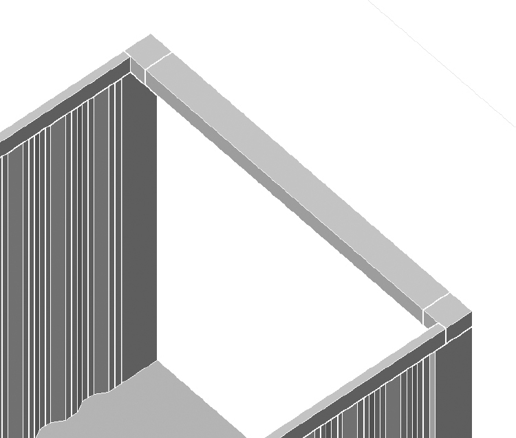
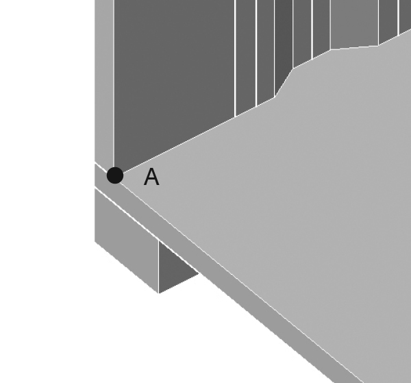
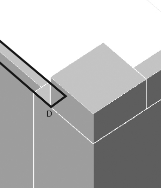
6.3 Place an instance of the wall.
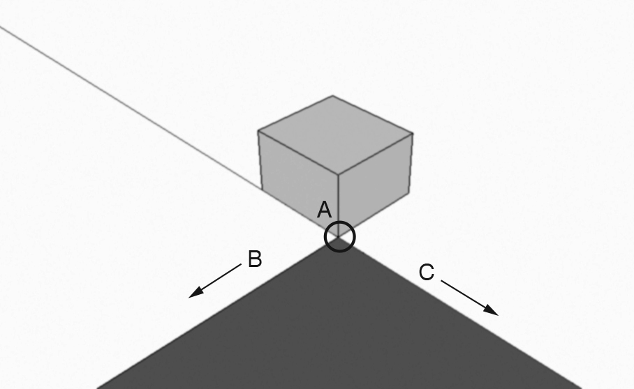
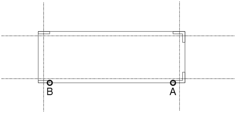
On the Architecture tab, Build Panel, choose the Wall: Architectural tool. On the Options bar, set the Height to Roof. Set the Location Line to Finish Face: Exterior. Check the “Chain” box off. Click on the point marked A in the diagram below to begin placing the wall. Click on point B to complete the wall. Then click on the Modify tool to complete the command. Height is a constraint. Any change to the location of the Roof level will affect the height of the walls constrained to it. (Choosing Unconnected for Height omits the constraint.) See [F1] > Revit Users > Build the Model > Architectural Modeling > Walls > Placing Walls.

6.4 Place two more instances of the wall.
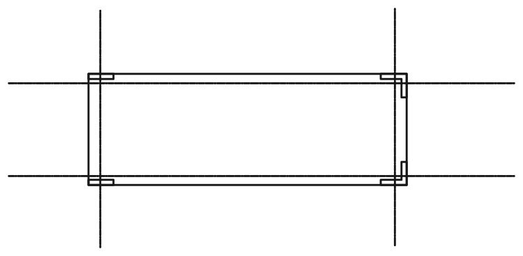
Repeat the previous step to place two additional instances of the wall. Choose the Default 3D view to check that the model corresponds with the diagram below. The Default 3D View is a quick way to get a 3D view of the project. Click on the house icon in the Quick Access Toolbar (top of screen). See [F1] > Revit Users > Introduction to Revit > User Interface > Quick Access Toolbar and [F1] > Revit Users > Document and Present the Project > 3D Views > Creating a Perspective 3D View.

6.5 Restore the Base floor plan.
Double-click on the Base Floor Plan.
6.6 Lock the wall ends to the gridlines, and the wall centerlines to the gridlines.
On the Annotate tab, Dimension panel, choose the Aligned tool, and use it to dimension the wall-end-to-gridline relationships, making sure to click the padlock symbol to “lock” the padlock. Repeat this procedure for the wall-centerlines-to-gridline relationships.
6.7 Check the walls for position and flexibility.
Use the Modify tool to select and move the gridlines. The walls should move together with each of the gridlines. If they do not, or if you see an error message about constraints, redo the previous steps.
6.8 Check the walls and corner posts for height conformance.
Double-click on the North Elevation to make that view current. Use the Modify tool to select and move the Roof Level up and down. Repeat this procedure with the East Elevation. In both views, the top of the walls and corner posts should move together with the Roof Level. If they do not, or if you see an error message about constraints, redo the previous steps.
7 CONSTRUCT ROOF:
7.1 Make the Roof plan current.
Double-click on the Roof Floor Plan.
7.2 Insert a corner_block component.
On the Architecture tab, Build panel, choose the Component > Place a Component tool. At the top of the Properties panel, click the type selector (it should currently display the corner_post_rear component). Change the type selector to the corner_block component. Insert this component at the lower left-hand corner of the Roof floor plan.
7.3 Correct the component’s height.
Use the Modify tool to select the component you just placed. In the Properties palette, check that its Base Level is set to Roof. Change its Top Offset to 4.5” (four-and-a-half inches).
7.4 Mirror the component.
Using a procedure similar to the one you had used with the original set of corner_block components, mirror the component to all four corners of the Roof floor plan.
7.5 Lock the components to the gridlines.
Use the same procedure you’ve used previously (Aligned dimensions with padlock symbols).
7.6 Make the Default 3D View current.
7.7 Construct walls between corner blocks.
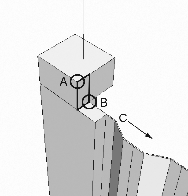
Using a procedure similar to the one you used earlier to construct the container’s side walls, use the Wall: Architectural tool to build four “rails” around the top edge of the container as shown in the diagram below. Note, when you begin constructing the first wall, set the Base Constraint to Roof, the Top Constraint to Unconnected, and the Unconnected Height to 4.5” (four-and-a-half inches).

7.8 Lock the wall ends and wall centerlines to the gridlines.
Use the Aligned dimension tool.
7.9 Make the Roof floor plan current.
Double-click on the Roof floor plan.
7.10 Begin to construct a roof.
On the Architecture tab, Build panel, choose the Roof > Roof by Footprint tool. See [F1] > Revit Users > Build the Model > Architectural Modeling > Roofs
7.11 Edit the roof type.
In the Properties palette, make sure the Basic Roof – Generic 12” type is current. Click the Edit Type button. In the resulting Type Properties dialog box, click Duplicate. Give the duplicate type the name Container – 4.5” and click OK. Still within the Type Properties dialog box, next to the Structure parameter, click Edit. Change the Thickness to 4.5” (four-and-a-half inches) and click OK. Click OK again to exit the Type Properties dialog box.
7.12 Outline the roof.
On the Modify | Create Roof Footprint tab, Draw panel, choose the Line tool. On the Options bar, check Defines Slope off; check Chain on. Use the Line tool to outline the roof as shown in the diagram below. By checking the “Defines Slope” option off, Revit will create a flat roof.

7.13 Lock the roof edges and corner notches to the gridlines.
Use the same procedure you’ve used previously (Aligned dimensions with padlock symbols). There will be a total of 12 dimensions: one on each roof edge, and two at each of the corner notches.
7.14 Complete the roof.
On the Modify | Create Roof Footprint tab, Mode panel, click the green check mark.
8 CREATE A DOOR:
8.1 Set the Base floor plan as current.
Double-click on the Base floor plan. See [F1] > Revit Users > Build the Model > Architectural Modeling > Doors > Placing Doors.
8.2 Adjust the gridlines to their correct positions.
Begin by using the Aligned Dimension tool to establish a dimension between any two parallel gridlines. Click the Modify tool. Then click on one of the gridlines you just dimensioned. Finally, click on the highlighted dimension to change its value. (The “long” dimension is 38’-4”, and the “short” dimension is 7’-5”.
8.3 Create a wall closing the open side.
On the Architecture tab, Build panel, choose the Wall: Architectural tool. Before placing the wall, check the Properties palette. The Base Constraint should be set to Base and the Top Constraint should be set to Up to Level: Roof.
8.4 Begin a New Family definition.
Under the [Application Menu], choose New Family. Choose the Door template file. Click Open.
8.5 Make the Exterior view current.
In the Project Browser, double-click on the Exterior Elevation view.
8.6 Modify the door frame.
In the elevation view, double-click on the extrusion representing the door frame. Double-click on the text reading Frame Width = 0’-3”. Change the frame width parameter to 1/2” (one-half inch). Click the green check mark (Modify | Edit Extrusion tab) to complete editing.
8.7 Set the door width and height as instance parameters.
Click on the text reading Width = 3’-0”. In the Options bar, check Instance Parameter on. Repeat this step for the Height.
8.8 Save the family.
Save this family as container_door.rfa.
8.9 Load the family into your project.
On the Modify tab, Family Editor panel, choose Load into Project (the .rvt file).
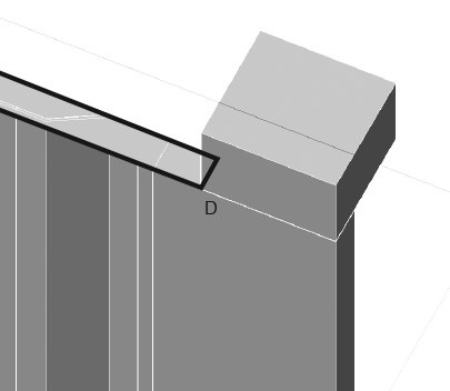
8.10 Place the door.
Insert the door at the midpoint of the wall you drew earlier. Click the Modify tool to complete the task.
8.11 Invoke the Default 3D view.
8.12 Modify instance properties.
Select the door. In the Properties palette, under Dimensions, change the Sill Height to 1”, the Height to 8’-3”, and the Width to 7’-0”.
8.13 The model is complete.