Scale Factor

Scale factor is a means of expressing the relationship between a measured object and its representation, or sometimes between a digital drawing and a printout.

Determine the scale factor for common architectural scales by expressing the scale designation as a ratio in the form of 1 : x, as shown here:

232-autocad-guide-04-38


Be aware of the visual meaning of scale factor:

ruler

Advertisement

AutoCAD: Object Snaps

Object snaps are used to create precise drawings. Use the [F3] key to turn the automatic object snap function on and off. When it’s on, this function automatically “locks” the drawing commands to predefined points (like endpoints and intersections of existing lines).

Type OSNAP at the command prompt to specify the points to which AutoCAD will automatically lock.

Even if the automatic object snap function is off, you can still force AutoCAD to temporarily lock to a specific point in the middle of a drawing command. While drawing, when you’re prompted to specify a point, type the first three letters of the desired snap function (e. g. END for endpoint, MID for midpoint, PER for perpendicular, etc.).

osnaps_01

Note: The NODe object snap locks to points. Points are zero-dimensional AutoCAD objects, the appearance of which is controlled using DDPTYPE. Use the DIVIDE command to automatically draw points at a whole number of equally-spaced divisions along a line, circle, or arc; use the MEASURE command to automatically draw points at predetermined equal intervals (e. g. every inch) along a line; lock to these points with the NODe snap.


TRACKING. The object snap tracking function ([F11]) extends the functionality of the basic object snaps. The tracking function “sees” distant points as you’re drawing. When it’s on, and while you’re drawing, move the mouse (without clicking) over a point, and then move the mouse away. The [F3] key must also be “on” in order for [F11] to work.


SCREEN CONTROLS. Related: Instead of clicking [F3], you can click the OSNAP button at the bottom edge of the screen. Instead of clicking [F11], you can click the OTRACK button.

AutoCAD: Saving and Opening Drawings

SAVING AUTOCAD DRAWINGS:

To save your work, choose [Application Menu] > Save. Always keep at least one fully updated backup copy of your work in a safe place (e. g. one copy on a flash drive and another copy stored online).


OPENING AUTOCAD DRAWINGS:

To open a saved drawing, choose [Application Menu] > Open.


DIFFERENT EDITIONS OF AUTOCAD:

If you intend to work between two different editions of AutoCAD (for example, edition 2015 at school and edition 2007 on Granny’s laptop), remember that the older edition of the software cannot read drawings produced by the newer edition unless the drawings are deliberately saved in a compatible format. To do this, choose [Application Menu] > Save As in any edition of AutoCAD; choose the appropriate format from the available list.

AutoCAD: Special Keys

In AutoCAD, the [Enter] key and the space bar, for most purposes, are identical in function. (For example, typing LINE followed by Enter is equivalent to typing L followed by the space bar.)

Typing the space bar at the Command prompt after a command is completed will repeat the last command typed.

Click the [esc] (escape) key two or three times in succession will cancel any command and return to the Command prompt.

Each of the function keys has a special function in AutoCAD.

Linetypes

CONVENTIONAL USES FOR LINETYPES:

Dashed lines are often used to indicate items above the plan cut or in front of the section cut, or objects below or beyond a visible surface.

A “center” linetype (a repeated pattern of single long dash and single short dash) is usually used to indicate gridlines or center lines of objects or spaces.

Specialty linetypes are often used by various engineering disciplines to indicate utility routes; such linetypes often consist of a dashed or broken line annotated with the service description.

Lineweights

Lineweight is the visual thickness of lines. The use of lineweight is critically important to maintaining good legibility and professional appearance in drawings.

The following pair of drawings of the Robie House in Chicago illustrate conventional uses of lineweights:


robie-plan


LINEWEIGHT CONVENTIONS:

Discerning objects cut by a plane. Relatively heavy lineweights (e. g. in excess of 0.5 mm) are usually used to designate objects cut by a plane. For example, in a plan drawing, a lineweight of 0.5 mm might designate walls and columns; in a section drawing, the same lineweight might designate floors, walls, and the ground.

Discerning changes in observable planes. Relatively medium lineweights (e. g. 0.3 mm or so) are usually used to designate objects observed against a background. For example, in a plan drawing, a lineweight of 0.3 mm might designate a countertop, an item of furniture, stairs, a balcony edge, and so on; in a section or elevation drawing, the same lineweight might designate the outline or edge of a wall against a distant wall, or an opening in a wall. In an axonometric drawing (such as the one of the Robie House to the left), a medium or heavy line might outline solid objects against a background.

Discerning changes in material occurring on a single plane. Relatively thin lineweights (e. g. less than .1 mm) are usually used to designate changes in material occurring on a single plane. For example, in a plan drawing, a lineweight of less than 0.1 mm might designate a threshold at a door, or the spring point of a ramp; in a section or elevation drawing, the same lineweight might designate trim around a door or window.

Designating material or texture. The thinnest possible lineweight (0 mm) is often, though not exclusively, used for hatch patterns in plans, sections, and elevations. Note that 0 mm does not indicate “no line”; rather, it indicates the thinnest line producible by the selected output device.

AutoCAD: Linetypes

Like lineweight, linetype is a property assigned to layers, and by extension, to objects assigned to those layers. Although it’s considered good practice to use layers to organize object linetype, object lineweight is often set on a per-object basis.


LINETYPE SCALE IN AUTOCAD.

All AutoCAD linetypes, with the exception of the default CONTINUOUS linetype, are subject to the LTSCALE system variable. As a general rule, if LTSCALE is increased, the size of the pattern (e. g. the dashes in the line) will increase. However, each different LINETYPE bears a different relationship to LTSCALE. For example, if you set LTSCALE to 1, the DASHED linetype looks like this:
linetype-dashed
Meanwhile, the HIDDEN linetype looks like this:
linetype-hidden
A good rule of thumb for LTSCALE is as follows. Consider the scale at which you’ll print the drawing. Convert this scale to a ratio (e. g. 1/4” = 1’-0” is equivalent to 1 : 48). Set LTSCALE to the right half of this ratio (in this example, to 48). This rule works because if you print your drawing at a comparatively small size, the dashes in the lines should be large relative to the size of objects in the drawing.


TO LOAD A LINETYPE INTO A DRAWING:
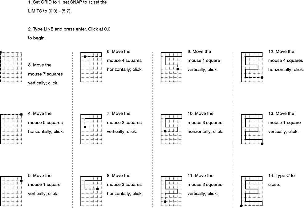
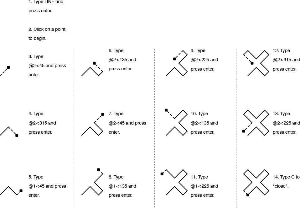
1.     Type LINETYPE.

2.     In the resulting Linetype Manager dialog box, click Load.

3.     Choose the linetype you want to load and click OK.

4.     Click OK again to close the dialog box. The linetype is now available to be assigned to layers and/or objects (see below).


TO CHANGE LINETYPE ON A PER-OBJECT BASIS:

1.     Load a linetype into your drawing. (See above.)

2.     From the View tab, Palettes panel, click Properties to display the Properties palette.

3.     Click on an object, or a group of objects. Click next to the word “Linetype” in the Properties palette and select a new linetype from the pulldown menu. Click the escape key to deselect the object(s).

AutoCAD: Layers

Every object in AutoCAD belongs to a layer. A layer can be made invisible, causing the objects assigned to that layer to disappear from view (this is called turning a layer off). A layer can be locked, protecting the objects assigned to that layer from accidental erasure or displacement. A layer can be defined as non-printing, so that its objects are visible on screen but do not print.


TO CREATE A NEW LAYER:

Type LAYER. In the resulting Layer Properties Manager dialog box, use the New button to create and name a layer; use the Current button to choose a layer for drawing (newly drawn objects appear on the current layer); use the color swatches to assign colors to layers.


TO DELETE A LAYER:

In the Layer Properties Manager dialog box, highlight a layer name and click Delete. If the layer contains objects, it cannot be deleted. Typing PURGE at the command prompt will omit unused layers.


TO CHANGE AN OBJECT’S LAYER:
Use any one of these methods:

Type CHANGE (or –CH). When prompted, select the object(s) and click enter. Type P for Properties; LA for Layer; and then the name of the layer to which you wish to assign the object(s).

OR use the layer pulldown menu in the Object Properties toolbar. Click the object(s); then click the pulldown menu and release the mouse over the layer to which you wish to assign the object(s). Click the escape key to deselect the object(s).

OR click ctrl-1 to display the Properties palette. Click on an object, or a group of objects. Click next to the word “Layer” in the Properties palette and select a layer from the pulldown menu. Click the escape key to deselect the object(s).

OR use the MA (“match properties”) command to assign the properties of a source object, including its layer assignment, to one or more other objects.


AutoCAD: Function Keys

In AutoCAD, the function keys (except for F1 and F12) act as switches or toggles. Of all the function keys, F3 (object snap) and F8 (“ortho”) tend to be the most frequently used. The others tend to be used comparatively rarely.

F1 brings up AutoCAD’s Help.

F2 opens and closes the Text window, which is simply an expanded version of the command window. It provides no additional functionality other than the ability to look back at what you just typed.

F3 turns the object snap function on and off.

F4 turns a peripheral drawing tablet (if connected) on and off.

F5 cycles between isometric planes. This function is used for creating isometric drawings. (To experiment with this, type SNAP, change the Style to Isometric, and draw some lines. Use F5 to cycle between planes.) Also see F9.

F6 cycles between coordinate displays, at the bottom left-hand corner of the screen.

F7 turns the drawing grid on and off. To specify the gird extents, type LIMITS. To specify the grid spacing, type GRID.

F8 turns the orthographic lock function on and off.

F9 turns the automatic snap function on and off. When on, AutoCAD snaps to an invisible rectangular or isometric grid, not necessarily the same grid as specified using the GRID command. To specify the snap settings, type SNAP.

F10 turns polar tracking on and off. It also automatically turns F8 (ortho) off. Polar tracking displays angles and distances while drawing.

F11 turns the automatic object snap tracking function on and off.

F12 has no function.